VoIP can sound perfect, then suddenly turn robotic. Most teams blame the SIP server first, but the real problem often lives in the media stream.
RTP delivers VoIP audio by sending small, time-stamped UDP packets that carry encoded voice frames. Sequence numbers detect loss and reordering, timestamps drive smooth playout, and jitter buffers hide timing noise without waiting for retransmissions.

How RTP Actually Moves Voice Across an IP Network
RTP is built for real time, not perfect delivery
RTP (Real-time Transport Protocol) 1 is designed for time-sensitive media. It usually rides on User Datagram Protocol (UDP) 2 because UDP does not wait for retransmissions. That choice protects conversational flow. The trade-off is simple: when packets are lost, they are gone. RTP expects the receiver to cope with loss and timing variation using a jitter buffer and packet-loss concealment (PLC).
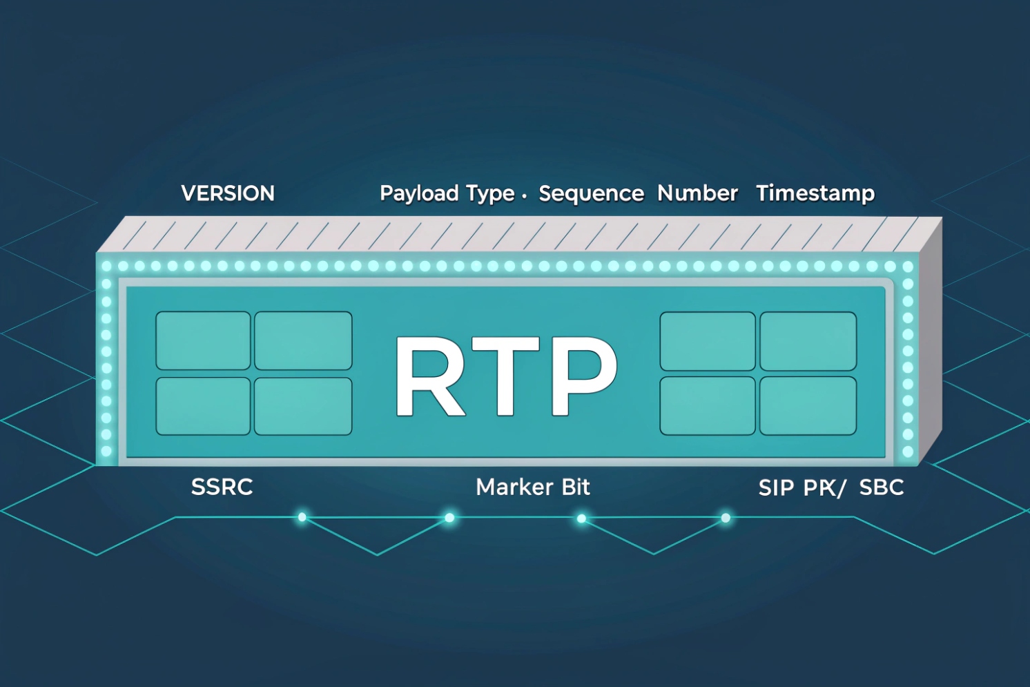
Each RTP packet has a header that helps the receiver rebuild timing and order. The key fields are the sequence number and timestamp. Sequence numbers let the receiver detect gaps and reorder out-of-order packets. Timestamps tell the receiver when a sample should be played, so audio stays steady even when network delay moves around. SSRC identifies the stream source, which matters when calls are mixed or bridged. The payload type tells the receiver which codec format is inside. Some payload types are fixed (like G.711), and many are dynamic and negotiated in SDP.
A normal call uses two one-way RTP streams. One stream carries audio from Phone A to Phone B. The other stream carries audio from Phone B to Phone A. Each direction uses its own UDP port, and those ports are usually negotiated during call setup.
| RTP header field | What it does | Why it matters for voice |
|---|---|---|
| Sequence number | Tracks packet order and loss | Detects missing audio frames |
| Timestamp | Drives playout timing | Smooths jitter, avoids “fast/slow” audio |
| Payload type | Identifies codec format | Lets endpoints decode the audio correctly |
| SSRC / CSRC | Identifies stream and contributors | Helps mixers, conferences, and analytics |
RTP is not “one protocol,” it is a framework
RTP defines transport rules and header structure, but audio behavior depends on the codec and the endpoint logic. A G.711 stream with 20 ms packets behaves differently from Opus with FEC enabled. RTP also has secure and extended modes. Secure RTP (SRTP) 3 adds encryption, integrity, and replay protection. Keys are commonly exchanged through DTLS-SRTP 4, especially in modern browser and WebRTC style deployments.
RTP is the workhorse of VoIP, but it does not work alone. RTCP provides the feedback loop that turns raw packets into measurable call quality.
If RTP is the “voice truck,” RTCP is the “dashboard.” The next sections explain how to read that dashboard, how to open firewalls safely, how NAT breaks media paths, and how to tune packet timing and MTU for stable audio.
How do RTP and RTCP work together for call quality?
Call quality problems feel random when there is no feedback. RTCP turns the media stream into numbers that can be acted on.
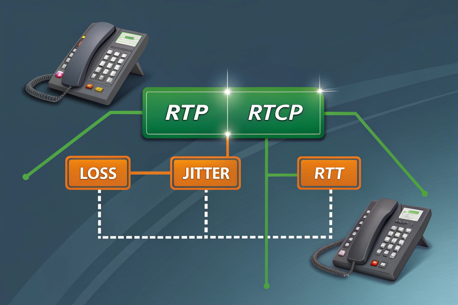
RTP carries the audio payload, while RTCP reports what the receiver experienced: loss, jitter, and timing. RTCP also helps estimate round-trip time and supports stream synchronization, so endpoints and SBCs can detect quality drops and adapt.
RTP delivers, RTCP observes
RTCP (RTP Control Protocol) runs alongside RTP. In classic designs, RTP uses an even UDP port and RTCP uses the next odd port. Many deployments also use RTCP multiplexing (rtcp-mux), where RTP and RTCP share one port. Both models exist in the field, so firewall policy should account for how the environment is built.
RTCP packets carry reports that summarize reception quality. The most common ones are Sender Reports (SR) and Receiver Reports (RR). Report blocks include metrics like fraction lost, cumulative packets lost, and inter-arrival jitter. These values help phones, soft clients, and SBCs detect degraded paths. RTCP also supports round-trip estimation using timing fields (LSR and DLSR), which is useful when diagnosing high-delay WAN links. If you want the canonical definitions for report types and fields, start with the RTCP Sender/Receiver Reports section of RFC 3550 5.
RTCP is not constant chatter. It is rate-limited by design, often targeting a small percentage of the session bandwidth. That keeps control overhead low while still providing useful visibility. When call analytics say “2% loss and 35 ms jitter,” it often comes from RTCP stats, not from ping.
| RTCP item | What it carries | What it helps diagnose |
|---|---|---|
| Receiver Report (RR) | Loss fraction, total loss, jitter | Choppy audio, burst loss, Wi-Fi issues |
| Sender Report (SR) | RTP-to-NTP timing, counts | Sync, timing drift, stats integrity |
| RTT estimation fields | LSR/DLSR timing data | Delay spikes, asymmetry, WAN congestion |
| SDES / BYE | Identity and session end | Stream mapping, clean teardown |
Why this matters in real deployments
In many enterprise and intercom projects, ping looks “fine” while audio breaks. RTCP helps prove what happened during the call. If loss is low but jitter is high, the fix is often queue management and Wi-Fi tuning, not codec changes. If loss jumps only on one direction, the issue is often NAT or firewall state, not a codec bug. This feedback is also how some systems trigger actions like switching codecs, enabling redundancy, or changing jitter buffer size.
When troubleshooting customer sites, the fastest path is usually: confirm RTP is flowing, then confirm RTCP shows stable loss and jitter. That keeps the conversation grounded in evidence instead of guesses.
Which RTP ports and codecs should I allow on firewalls?
Many “VoIP firewall rules” are too broad. Others are too strict. The goal is controlled openness: allow what media needs, and nothing more.
Allow UDP for the RTP/RTCP port range your PBX/SBC and endpoints actually use, plus the negotiated codecs and DTMF payloads in SDP. Keep the range narrow, prefer an SBC at the edge, and avoid relying on SIP ALG to “fix” media.
Ports are negotiated, so the range matters
RTP ports are usually dynamic. SIP/SDP tells the far end which IP and port to send media to. Because of that, firewalls often need to allow a defined UDP range, not one single port. The exact range depends on platform defaults and configuration. Common examples in the field include 10000–20000, 16384–32767, or high ephemeral ranges. The best practice is to set an explicit media range on the PBX/SBC and on endpoints where possible, then allow only that range.
RTCP may use the next port after RTP, but RTCP-mux can remove the need for separate RTCP ports. If the environment mixes device types, planning for both models avoids surprises.
Also remember DTMF. Many SIP deployments use RFC 4733 telephone-event RTP payload 6 as an RTP payload. If DTMF fails, the “codec list” might be fine, but the telephone-event payload is missing or blocked by misbuilt SDP policies.
| Item to allow | Typical pattern | Notes that prevent outages |
|---|---|---|
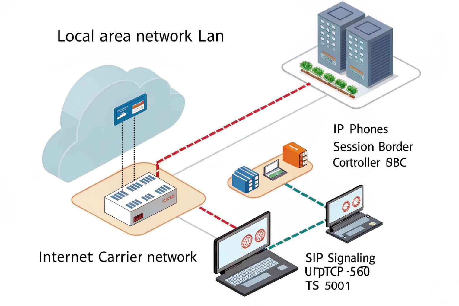
| SIP signaling | UDP/TCP 5060, TLS 5061 | Depends on system, not RTP, but needed for setup |
| RTP media | UDP port range (configured) | Keep it narrow and documented |
| RTCP | Adjacent ports or rtcp-mux | Match your endpoints and SBC behavior |
| DTMF | RTP telephone-event payload | Often required for IVRs and door release |
| SRTP | Same ports as RTP, but encrypted | Needs keying method support (often DTLS-SRTP) |
Codec choices affect bandwidth and tolerance
Firewall rules do not “allow a codec” directly. The codec is negotiated in SDP, then carried inside RTP. Still, codec policy matters for network design and for what gets offered in call setup. A practical baseline for interoperability is G.711 (PCMU/PCMA) for maximum compatibility, plus a modern option like Opus where supported. For wideband voice, G.722 is common in enterprise phones. If bandwidth is limited, compressed codecs can help, but some are more sensitive to loss.
From product integration work, the simplest rule set is usually: keep SIP and RTP predictable, keep the media range stable, and let the codec list be controlled on the PBX/SBC. That approach prevents “works on LAN, fails on WAN” cases caused by random port use.
How do NAT and SIP/SDP affect RTP media paths?
NAT is the main reason “registration works but audio fails.” RTP depends on correct address and port information, and NAT often breaks that information.
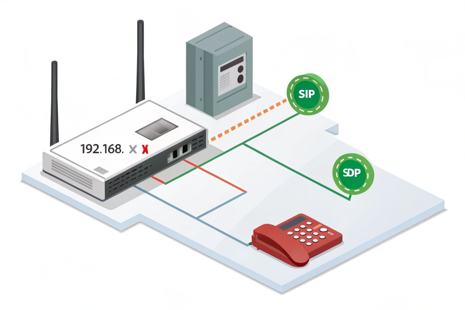
SIP negotiates RTP using SDP, which includes the media IP and UDP port. NAT can cause private IPs in SDP, wrong return paths, or expired UDP mappings, leading to one-way audio or no audio. Use SBCs, ICE/STUN/TURN where suitable, and symmetric RTP/keepalives to keep paths open.
SDP tells the far end where to send media
During call setup, SDP carries lines that matter for RTP routing. The c= line declares the connection address. The m=audio line declares the media port and transport profile. Payload types and codec mapping are listed, often using rtpmap and related attributes. If a phone behind NAT advertises its private IP in c=, the far end may send RTP to an unroutable address. That creates dead air even when SIP signaling is fine.
SIP devices and SBCs handle this in different ways. Many systems rewrite SDP at the border. Some rely on SIP ALG in routers, but that often causes more harm than good because it rewrites headers in ways modern SIP stacks do not expect. A controlled SBC or session-aware firewall policy is usually more stable than a generic ALG.
Why one-way audio happens
One-way audio often means RTP is flowing in one direction only. Common causes include:
- NAT mapping exists for outbound RTP, but inbound RTP is blocked
- The far end sends to the wrong IP/port because SDP was wrong
- Firewall state times out because UDP is idle or keepalives are missing
- Asymmetric routing sends return RTP through a different gateway
Symmetric RTP (sometimes called “comedia” in SDP terms) can help. In symmetric RTP, the receiver sends media back to the source IP/port it actually observed, not the one claimed in SDP. This can save calls when NAT rewriting is inconsistent.
| NAT/SDP problem | What it looks like | Fix pattern that works |
|---|---|---|
| Private IP in SDP | No audio or one-way audio | SBC SDP rewrite, correct NAT settings |
| UDP mapping timeout | Audio drops after some seconds/minutes | RTP keepalive, longer UDP timers |
| Wrong media path | Audio only in one direction | Symmetric RTP, correct routing, ICE |
| Hairpin/NAT loop | Internal calls fail via public IP | Split DNS, proper hairpin support |
ICE/STUN/TURN and modern media
In WebRTC and some modern clients, ICE gathers candidate paths. STUN discovers public reflexive addresses. TURN relays media when direct paths fail. These tools improve media success rates across complex NAT. A good starting reference is ICE (Interactive Connectivity Establishment), RFC 8445 7. They add complexity, but they solve the “RTP cannot find a path” problem in a structured way.
For SIP intercom and access control deployments, the cleanest design is often: keep endpoints on a stable LAN, place an SBC at the edge, and make NAT behavior predictable. That design reduces late-night “one-way audio” tickets.
What packetization, jitter buffer, and MTU settings optimize RTP?
Small tuning choices create big differences. Packetization, jitter buffer size, and MTU shape how fast and how stable audio feels.
Use ~20 ms packetization for a balanced latency/overhead trade, set adaptive jitter buffers with safe max limits, and avoid IP fragmentation by keeping packets under the real path MTU. Stable timing beats ultra-low delay in most business VoIP.
Packetization time is a trade, not a rule
Packetization time (ptime) is how many milliseconds of audio are put into each RTP packet. Around 20 ms is common because it balances overhead and latency. Shorter ptime (10 ms) reduces mouth-to-ear delay and can help with fast talkers, but it doubles packets per second and increases header overhead. Longer ptime (30 ms or 40 ms) reduces overhead, but it increases latency and makes loss events more audible because each lost packet removes a larger chunk of speech.
| Packetization | Packets per second | Pros | Cons |
|---|---|---|---|
| 10 ms | ~100 pps | Lower codec delay, smoother for tight buffers | More overhead, more CPU and Wi-Fi airtime |
| 20 ms | ~50 pps | Balanced and widely compatible | Not the lowest possible delay |
| 30 ms | ~33 pps | Less overhead | Higher latency, harsher loss impact |
In many site deployments, 20 ms stays the safest default. It also keeps interoperability simple across mixed phone brands, intercoms, and SBCs.
Jitter buffer tuning should match the network reality
A jitter buffer smooths packet arrival variation. If the network is stable, a small buffer keeps delay low. If the network is unstable, a small buffer causes late drops that sound like loss. Adaptive jitter buffers help because they expand during rough periods and shrink during calm periods.
Still, a jitter buffer needs limits. A buffer that grows too large makes conversations feel delayed. A buffer that is too small makes audio choppy. For enterprise and building intercom scenarios, stability usually matters more than shaving a few milliseconds. Clear audio beats “fast but broken” audio.
MTU and fragmentation: avoid silent media loss
Most voice RTP packets are small, so MTU is rarely a problem for audio alone. Problems appear when VPN overhead shrinks the effective MTU, or when secure modes and additional headers stack up. If packets fragment and the network drops fragments, audio holes appear. Path MTU discovery can fail in some networks, which creates black-hole behavior. The practical fix is to avoid large packets in the first place and keep the network consistent end to end.
A simple field rule works well: keep RTP packet sizes comfortably under Ethernet MTU, and be extra careful on VPN and cellular paths. When video is added, or when WebRTC is used, the “safe” size often needs to be smaller because of different encapsulations.
| Setting area | Good starting point | What to watch in real calls |
|---|---|---|
| Packetization (ptime) | 20 ms | Bandwidth use, loss sensitivity |
| Jitter buffer | Adaptive, moderate max | Late drops vs added delay |
| MTU path | Avoid fragmentation | VPN links, ICMP blocked PMTUD |
| QoS marking | DSCP EF for voice | Correct mapping on Wi-Fi and WAN |
For DJSlink-style SIP intercom and emergency endpoints, these tuning rules reduce surprise failures. When audio is needed at the door or at a help point, stability and predictability matter more than theoretical best-case latency.
Conclusion
RTP carries VoIP audio as time-stamped UDP packets, while RTCP reports loss and jitter. Stable ports, correct NAT handling, and smart packetization/jitter buffer tuning keep real-time voice clear.
Footnotes
-
RTP spec: header fields, timing model, and core behavior for real-time media streams. ↩ ↩
-
UDP spec: why VoIP prefers low-latency delivery over retransmissions. ↩ ↩
-
SRTP spec: encryption, integrity, and replay protection for RTP media. ↩ ↩
-
DTLS-SRTP spec: standard keying method widely used for secure RTP sessions. ↩ ↩
-
RTCP report fields: how loss, jitter, and timing are summarized for quality troubleshooting. ↩ ↩
-
DTMF over RTP: telephone-event payload details for IVRs, door release, and tone signaling. ↩ ↩
-
ICE spec: how STUN/TURN candidates establish media paths across NAT reliably. ↩ ↩


