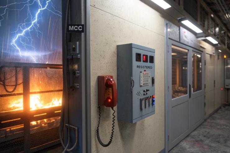
A hazardous-area phone can be perfectly certified and still crash when a contactor switches. That gap turns a safety device into silence.
An explosion-proof telephone should meet IEC 61000-4-4 EFT levels that match the site class, usually industrial, then prove Criteria B recovery on every connected port without losing configuration.

EFT for Ex Telephones: Set the Level by Environment and Ports
Explosion-proof is about ignition, EFT is about uptime
Explosion-proof certification controls ignition risk. It does not guarantee the device will keep working during electrical noise. EFT is part of EMC immunity. It targets fast switching events from relays, motors, solenoids, and VFD systems. These events hit cables as short, repeated bursts. A metal enclosure helps, but it does not solve everything. The noise still enters through the ports. The ports include PoE Ethernet 1, 24 VDC power, dry contacts, sensor inputs, strobe outputs, and sometimes RS-485. Each port has a different coupling path. Each path needs its own test level and pass criteria.
A good spec starts with the environment. A refinery, chemical plant, mine, and pipeline station are usually “industrial EMC” by practice. The next step is to set a target level per port. Many buyers only write one line like “EFT 4 kV.” That line is incomplete because IEC 61000-4-4 2 assigns different levels for power and signal lines. The phone can pass 4 kV on DC power and still fail at 1 kV on a long I/O line, because the I/O line couples straight into logic pins.
In one commissioning case, a site had clean SIP and strong PoE switches. The phone still rebooted during a pump start. The root cause was a long alarm cable tied to a motor tray. The phone hardware was fine, but the port protection and earthing plan were not aligned. This is why the spec must treat the phone and installation as one system.
A simple way to decide the target level
Use this quick table to set a starting point, then adjust by risk and cable exposure.
| Port type | Cable reality on site | Starting EFT target | Why it is reasonable |
|---|---|---|---|
| PoE Ethernet | In trays with other LV cables | ±1 kV (signal/control) | Noise enters as common-mode bursts |
| 24 VDC power | From panel supply | ±2 kV (power) | Switching noise rides on DC rails |
| I/O (inputs/outputs) | Long runs, field wiring | ±1 to ±2 kV (signal/control) | Long loops pick up bursts easily |
| Short internal patch leads | Inside cabinet | Lower may be acceptable | Less coupling area |
This approach keeps the spec clear and easy for a lab to execute. It also matches how failures happen in the field. A strong EFT spec is not about chasing the highest kV number. It is about making sure the device stays usable, recovers on its own, and leaves a log that explains what happened.
If the next sections feel detailed, that is good. EFT problems are rarely solved by one part. They are solved by correct standards, correct test setup, clear pass criteria, and clean wiring rules.
Which standards define EFT—IEC 61000-4-4 test levels, burst frequency, and coupling/decoupling for PoE, 24 VDC, and I/O?
EFT talk gets messy fast because people mix methods, levels, and fixtures. A phone can “pass” in one lab and fail in another.
IEC 61000-4-4 defines the EFT waveform and test method, then port-specific coupling is done using CDNs for power and clamps or networks for signal lines like PoE and I/O.

The core standard: IEC 61000-4-4
IEC 61000-4-4 is the test method standard for Electrical Fast Transient / Burst immunity. It defines the pulse shape, rise time, burst structure, repetition, and the severity levels in kV. It also defines how the disturbance is coupled to the equipment under test. This matters because a bad coupling setup can make tests too easy or unrealistically hard.
IEC 61000-4-4 uses two common internal burst frequencies: 5 kHz and 100 kHz. Labs often choose 5 kHz as a baseline for many industrial products. Some customers ask to test both, because some power designs react differently at 100 kHz. The standard also defines burst trains that repeat over time. This pattern matches real switching noise, where transients come in clusters, not as a single spike.
Coupling methods by port
A phone has several “ports,” and IEC 61000-4-4 treats them differently.
-
Power ports (AC or DC): A coupling/decoupling network (CDN) is used. The CDN injects EFT onto the line while keeping the supply stable and protecting other equipment in the lab.
-
Signal and control lines: A capacitive coupling clamp is common. It injects common-mode bursts along a cable length in a repeatable way.
-
Ethernet/PoE: Many labs inject with a clamp on the Ethernet cable for common-mode bursts 3. For PoE cases, the setup must also keep PoE negotiation and link behavior realistic. Some labs use dedicated fixtures or networks for data ports to avoid breaking the link in an artificial way.
What to write in a purchase spec so the lab cannot misread it
A good spec line includes: port list, coupling method, burst frequency choice, and dwell time.
| Item to specify | Good wording | Why it prevents disputes |
|---|---|---|
| Standard | “IEC 61000-4-4” | Everyone uses the same method |
| Frequency | “5 kHz (and 100 kHz if required)” | Avoids hidden assumptions |
| Ports | “PoE Ethernet, 24 VDC, all external I/O” | Stops partial testing |
| Coupling | “CDN on power, clamp on signal/data” | Keeps setup consistent |
| Test duration | “Minimum 1 minute per polarity per port” | Avoids short, weak tests |
This makes the test repeatable and auditable. It also makes it easier to compare suppliers. A phone that passes a vague EFT statement can still be risky. A phone that passes a clear method statement is easier to trust in a plant.
What kV levels are typical—±1/2/4 kV on power lines and ±0.5/1/2 kV on signal lines?
Many specs list one kV value without saying “power” or “signal.” That mistake creates wrong expectations and wrong test plans.
Typical industrial targets are ±2 kV on DC power ports and ±1 kV on signal/control ports, with higher levels used for long outdoor cables or heavy switching areas.
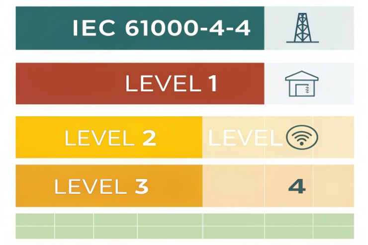
IEC 61000-4-4 level families
IEC 61000-4-4 defines common test levels. Many labs and spec sheets use these families:
-
Power lines: 0.5 kV, 1 kV, 2 kV, 4 kV
-
Signal/control lines: 0.25 kV, 0.5 kV, 1 kV, 2 kV
That is why “4 kV” alone is not complete. 4 kV is a power-line level, not a signal-line level in the common table. For a PoE phone, the Ethernet cable is a data port. The injected level usually maps to the signal/control group, even though PoE carries DC.
A practical “industrial plant” baseline that fits most Ex telephone deployments
Most industrial projects want stability during switching, not lab trophies. A strong baseline that stays realistic is:
-
24 VDC power input: ±2 kV
-
Ethernet/PoE: ±1 kV
-
Long external I/O lines: ±1 kV, and consider ±2 kV if cables leave the local bonding zone
This profile matches how noise enters. DC rails get hit hard when panels switch. Ethernet sees common-mode bursts from cable trays and ground shifts. I/O lines are often the worst because they connect to field devices and run near high current paths.
When to require higher than baseline
Push levels up when the site has more coupling risk:
-
Outdoor pipe racks with long cable runs
-
Motor control centers with frequent switching
-
VFD output cables nearby
-
Lightning-prone regions where surge protection is stressed
-
Remote I/O leaving a cabinet without proper shielding
In these cases, the phone should still be tested at realistic levels for its port category. A better step is to improve installation and SPD coordination, then test again, instead of only raising kV numbers.
A simple selection table for buyers and integrators
Use this table as a clean, defensible spec choice.
| Deployment condition | Power port target | Signal/PoE/I/O target | Notes |
|---|---|---|---|
| Indoor, short cables, clean trays | ±1 kV | ±0.5 to ±1 kV | Often acceptable in control rooms |
| Typical industrial plant | ±2 kV | ±1 kV | Good default for Ex phones |
| Heavy switching, long cables | ±4 kV | ±2 kV | Needs strong protection and wiring rules |
This keeps the conversation focused on risk and layout, not only on marketing numbers. It also helps procurement avoid overpaying for levels that do not reduce downtime.
How are pass criteria verified—performance Criteria A/B/C, functional recovery, and logs across temperature extremes?
A phone can “pass” while still rebooting, losing SIP, or dropping alarm outputs. That kind of pass does not protect a plant.
Verification should combine IEC performance Criteria A/B/C with real phone functions like registration, call setup, audio, and I/O stability, then confirm automatic recovery with logs and no configuration loss.
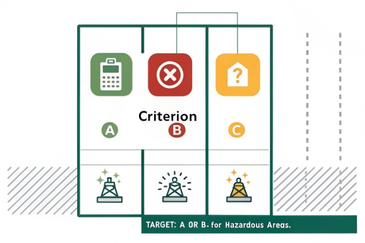
Criteria A, B, and C in plain terms
IEC immunity standards often use three performance criteria:
-
Criteria A: The device works as normal during the test.
-
Criteria B: The device may show a temporary issue, but it returns to normal on its own after the disturbance.
-
Criteria C: The device may stop or lose function and needs manual action to recover.
For an industrial explosion-proof certification 4, Performance Criteria B 5 is often the minimum acceptable target for EFT. Criteria A is ideal for some functions, but it can be hard to guarantee during strong bursts, especially on long field wiring. Criteria C is risky because an operator may not be near the phone to reboot it.
Convert criteria into measurable phone behaviors
A good test plan defines what “works” means for a phone. These checks are clear and easy to repeat:
-
The phone keeps its configuration. No reset to defaults.
-
The phone does not lock up. The keypad and hookswitch stay responsive.
-
SIP registration returns within a defined time after bursts stop.
-
A call can be placed and received after recovery.
-
Audio path works. No stuck one-way audio.
-
I/O does not false trigger. Relays do not latch in the wrong state.
-
The device does not reboot, or reboots only if allowed and recovers without manual action.
Logging and evidence that matter in audits
Many buyers accept a test report that says “PASS.” That is not enough for harsh sites. A stronger approach requests logs and timestamps.
| Evidence item | What it proves | How it helps field teams |
|---|---|---|
| System event log | Reboot, watchdog, brownout | Finds weak power paths |
| SIP registration log | Register, failover, retry | Shows recovery speed |
| Link status log | Ethernet up/down, PoE state | Separates network vs device issues |
| I/O state log | Input changes, relay actions | Detects false alarms |
| Configuration checksum | No hidden reset | Protects long-term stability |
Temperature extremes and real-world confidence
Most EMC labs test at room conditions. Harsh sites also care about cold starts, hot cabinets, and condensation risk. A practical way to cover this without breaking budgets is:
-
Run standard EFT at ambient per IEC method.
-
Run functional checks at low and high temperature points.
-
If the project is safety critical, run a reduced EFT spot check at temperature in a chamber, then confirm recovery again.
This approach avoids false confidence. It also matches what causes real failures. Many resets are not only EFT. They are EFT plus marginal power rails at low temperature, or plus thermal stress on DC/DC converters.
What design and installation measures improve EFT robustness—TVS arrays, common-mode chokes, shielded cabling, earthing, and SPD coordination?
EFT issues are often blamed on the phone, but many failures come from the cable path and bonding plan. Good hardware needs good installation.
Robustness comes from layered protection at every port, clean return paths to chassis, strong filtering, and correct field practices like shield termination, earthing, and coordinated SPDs on power and PoE.
Device design measures that change test outcomes
EFT is fast. The best parts are the ones designed for high-frequency energy.
-
TVS arrays 6 on exposed ports: Use low-capacitance TVS for Ethernet pairs. Use higher power TVS for DC rails and I/O.
-
Common-mode chokes on Ethernet and long I/O: These block common-mode bursts before they hit sensitive silicon.
-
Port entry filtering on DC power: Use LC or pi filters near the connector. Place bulk and ceramic decoupling close to converters.
-
Clear chassis bonding strategy: Route transient current to chassis and earth on purpose. Do not let it flow through codec or MCU grounds.
-
Isolation where needed: Opto-isolation or digital isolation helps when I/O leaves the local bonding zone, or when ground shifts are expected.
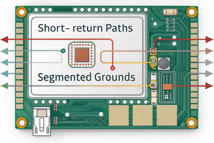
PCB layout rules that often matter more than the BOM
A strong BOM can still fail if layout is weak. These layout rules reduce upset and resets:
-
Keep the “dirty area” near connectors separate from the “clean area” near MCU and audio.
-
Use short, wide paths for transient currents to chassis reference.
-
Use stitching vias and solid planes to lower impedance.
-
Avoid long, high-impedance traces from connectors to logic pins.
-
Protect reset lines and clock lines with proper filtering and routing.
Installation measures that prevent most field failures
Installation quality often decides if a phone is stable in a plant. These steps are simple and effective:
-
Use shielded twisted pair 7 where possible, and keep pairs intact to the termination.
-
Terminate cable shields correctly. Use 360-degree shield bonding at glands when possible. Avoid long pigtails for high-frequency noise.
-
Keep equipotential bonding strong. Bond cabinets, trays, and local earth points so ground shifts stay small.
-
Separate routing. Keep phone and I/O cables away from motor feeders, contactors, and VFD output cables.
-
Use SPDs as a system. Place upstream SPDs at service entry and distribution, then use local protection near the device where exposure exists.
-
Coordinate PoE protection. If PoE lines run outdoors or between buildings, add PoE-rated surge protection and bond it correctly.
SPD coordination matters more than “one big protector”
Many sites install one SPD and expect it to solve everything. EFT and surge energy still travels. Coordination means each stage clamps part of the energy, so the device TVS does not take repeated stress.
| Layer | Location | Goal | Typical mistake |
|---|---|---|---|
| Primary SPD | Building/service entry | Stop large energy | No bonding plan, high impedance earth |
| Secondary SPD | Distribution panels | Reduce residual | Wrong SPD type for DC/PoE |
| Local protection | Near phone or cabinet | Protect the port | Protector mounted but not bonded well |
| Device TVS/filter | Inside phone | Final defense | Overloaded due to poor upstream SPD |
When these layers work together, EFT tests get easier to pass, and field stability improves. This also reduces hidden costs, like truck rolls and lost production time from communication downtime.
Conclusion
Explosion-proof phones need industrial EFT immunity by IEC 61000-4-4, clear port-level kV targets, Criteria B recovery proof, and strong wiring, bonding, and SPD coordination to stay reliable.
Footnotes
-
Technology that enables Ethernet cables to carry both data and electrical power to networked devices. ↩ ↩
-
An international standard defining immunity requirements for electrical equipment against fast transient electrical disturbances. ↩ ↩
-
Electrical interference that occurs simultaneously on multiple conductors, often caused by external electromagnetic noise. ↩ ↩
-
The global standard for certifying equipment used in explosive atmospheres to ensure safety and compliance. ↩ ↩
-
Defines acceptable device behavior where temporary degradation occurs but self-recovers after the interference stops. ↩ ↩
-
Electronic components designed to protect sensitive circuits from high-voltage spikes and transient electrical surges. ↩ ↩
-
High-quality cabling with internal shielding to reduce electromagnetic interference and ensure stable data transmission. ↩ ↩


