A hazardous-area phone can talk SIP perfectly and still stay “invisible” to SCADA. That blind spot delays alarms, tests, and emergency response.
Some explosion-proof telephones support Modbus, but most projects use Modbus through a gateway: Modbus TCP on Ethernet for modern networks, or Modbus RTU over RS-485 when the plant standard demands it.

Modbus and SIP can coexist, but the integration path must be planned
Modbus support is not universal in Ex phones
Many explosion-proof telephones are built for voice first. They focus on SIP calling, loud audio, rugged keys, and Ex compliance. Modbus is a control and monitoring protocol. Some models include it as a feature. Many do not. In most real deployments, Modbus comes from an integration layer, not from the phone itself.
The easiest integration layer is the phone’s dry contacts (relay outputs and digital inputs) plus a small Modbus I/O gateway. The gateway converts “contact open/close” into Modbus coils, and it can also accept Modbus commands and drive a relay. This path works with almost any phone because it does not depend on a special firmware feature.
The second integration layer is IP-based telemetry such as HTTP APIs, SNMP traps 1, or syslog events. A software gateway can convert those events into Modbus registers. This gives more details than a single relay, like “registered / unregistered,” “call state,” “tamper,” “PoE status,” or “self-test fault.” It also needs more engineering and network access.
The third path is native Modbus in the phone. It is clean when it exists. It is also the rarest. When a tender asks “Modbus required,” it is smart to clarify whether native Modbus is mandatory, or whether a certified gateway solution is acceptable.
Pick the architecture first, then write the register list
A good Modbus plan starts with one question: “What must the control room see and what must the control room control?” Most sites only need a short list:
- SOS pressed
- Off-hook / in-call
- Device fault
- Relay output state
- Optional: network link and power status
After that, the project can choose the simplest method that meets it.
| Integration approach | What it uses | Best for | What to watch |
|---|---|---|---|
| Dry contact → Modbus gateway | Relay + DI/DO gateway | Fast, universal, simple | Limited data points |
| API/SNMP/syslog → SCADA systems 2 software | Network events → registers | Rich status and logs | Needs IT access and security controls |
| Native Modbus TCP/RTU in phone | Built-in stack | Cleanest wiring and mapping | Vendor-specific register map |
A clear plan also avoids scope creep. If SCADA asks for “audio level,” define whether that means a setting value (volume level) or a real-time measurement (RMS). Most phones can provide settings. Few provide real-time audio metrics in a stable way.
The next section breaks down the Modbus variants and how they fit hazardous-area phones.
Which Modbus variants are available—Modbus TCP over Ethernet or Modbus RTU via RS-485 gateways?
Modbus is simple, but plants are not. Some sites are all Ethernet. Some still trust RS-485 for every signal.
Modbus TCP is usually the best fit when the phone already has Ethernet for SIP and PoE. Modbus RTU is usually done through an RS-485 gateway, because most Ex telephones do not expose RS-485 directly.
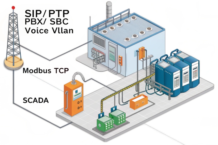
Modbus TCP 3 runs over the same Ethernet used by SIP, which is attractive because it avoids extra cable entries and extra glands. In practice, it works well when:
- the plant allows the phone VLAN to talk to SCADA VLAN through a firewall or ACL
- polling rates stay reasonable
- the phone CPU is not overloaded by heavy polling
If the phone does not support native Modbus TCP, a small edge gateway can still do Modbus TCP on the SCADA side and read phone states via contacts or API. This keeps SCADA simple, because SCADA only sees Modbus.
Modbus RTU: use RS-485 where the plant standard demands it
Modbus RTU is still common in some Distributed Control Systems (DCS) 4 and legacy SCADA designs. An Ex telephone rarely provides a direct RS-485 standard 5 port that the end user can wire without adding certification complexity. The normal pattern is:
- phone relay/contact → RS-485 remote I/O or gateway in a safe area
- gateway speaks Modbus RTU on the control bus
When the gateway is in a safe area, it is also easier to service and replace. The phone stays a voice endpoint, and the gateway becomes the “instrumentation” node.
A practical selection guide
| Site condition | Better choice | Why |
|---|---|---|
| SIP phones already on PoE Ethernet | Modbus TCP (native or via gateway) | One network path, simple wiring |
| Long distances with noisy trays | RS-485 Modbus RTU (gateway near phone cabinet) | RS-485 can be very robust with good practice |
| Strict OT isolation rules | Gateway near PLC/SCADA side | Keeps phone VLAN isolated |
| Many data points needed | API/SNMP → Modbus software | More status without extra wiring |
Every additional interface can add risk in hazardous areas. Extra ports mean extra glands. Extra glands mean more corrosion points and sealing points. This is why many offshore projects keep the phone wiring minimal and push protocol conversions into safe-area cabinets.
What registers and coils map phone status—hook, SOS, fault, relay I/O, and audio levels?
A good register map is small, stable, and easy for operators to understand. A bad map is huge and never used.
The best Modbus map for an explosion-proof telephone starts with coils for discrete states (SOS, off-hook, fault) and a few holding registers for settings (volume, ringer mode), while leaving complex call details to SIP logs or the voice platform.
Keep the first version simple: the “six signals” rule
In many plants, six signals cover 90% of the value:
1) SOS active
2) Off-hook
3) In-call
4) Phone fault
5) Relay output state
6) Tamper / door open (if supported)
These are discrete. They fit well as Modbus coils or discrete inputs. They are also easy to test during commissioning.
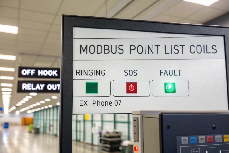
Example mapping template (vendor-neutral)
| Function | Modbus type | Example address | Meaning |
|---|---|---|---|
| SOS active | Coil | 00001 | 1 = SOS triggered |
| Off-hook | Coil | 00002 | 1 = handset lifted |
| In-call | Coil | 00003 | 1 = call established |
| Fault | Coil | 00004 | 1 = device fault present |
| Relay 1 state | Coil | 00005 | 1 = relay energized |
| Tamper | Coil | 00006 | 1 = cover opened / switch tripped |
Use fail-safe logic when mapping alarms
If a coil represents a safety alarm, define a fail-safe strategy. A common method is to wire the source contact as NC so that a broken wire becomes an alarm. If the mapping comes from software events, add a heartbeat register that SCADA watches.
How is Modbus security handled—TLS VPNs, network ACLs, segmentation, and read/write permissions?
Modbus is popular because it is simple. That also makes it weak if it sits on an open network.
Modbus security is handled by design around it: VLAN segmentation, strict ACLs, firewall rules, VPN tunnels where needed, and a policy that limits write access to only a few trusted hosts or disables writes entirely.
Assume Modbus has no built-in protection
Classic Modbus has no strong authentication and no encryption. That means anyone with access to the network path can read status and may be able to write coils or registers. For a phone, a write could trigger a relay output or disrupt monitoring.
A practical security model that passes audits
A clean model is:
- Put phones on a Voice VLAN.
- Put SCADA polling on an OT VLAN.
- Allow only a gateway or firewall-controlled route between them.
VLAN segmentation 6 is the preferred method for limiting lateral movement and improving overall network stability.
| Control | What to do | Why it helps |
|---|---|---|
| Segmentation | Separate VLANs for voice and OT | Limits lateral movement |
| ACLs | Allow only SCADA/gateway IPs | Blocks casual access |
| Firewall | Log and rate-limit Modbus flows | Reduces scan and flood risks |
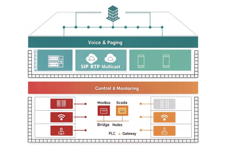
Can Modbus integrate with SCADA/DCS and coexist with SIP traffic, VLAN/QoS, and multicast paging?
Some teams fear that “more protocols” will break voice. That fear is valid when networks are flat and unmanaged.
Yes, Modbus can integrate with SCADA/DCS and coexist with SIP when voice and control are segmented by VLAN, voice is prioritized with QoS, Modbus polling is rate-limited, and multicast paging is managed with IGMP and clear switch settings.
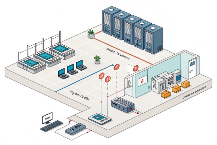
Integration patterns that work in real plants
Integration usually follows clear network hierarchies. Voice RTP is sensitive to delay and jitter, while Modbus is not. So the network should prioritize voice.
IGMP snooping 7 is critical to prevent multicast paging from flooding the VLAN and raising latency for Modbus traffic.
A “coexistence checklist” that saves commissioning time
| Topic | Target | Why it matters |
|---|---|---|
| VLAN design | Separate voice and OT | Limits noise and improves security |
| QoS | Prioritize RTP and SIP | Protects call quality |
| Polling | Rate-limit Modbus | Prevents CPU and link load spikes |
| Paging | IGMP snooping and group plan | Prevents multicast flooding |
Conclusion
Explosion-proof telephones can work with Modbus, but the most reliable path is a small gateway, a short register map, strong segmentation, and QoS rules that protect SIP and paging first.
-
Explanation of SNMP traps used for asynchronous notifications from network devices to a management system. ↩ ↩
-
A comprehensive overview of Supervisory Control and Data Acquisition systems used to monitor and control industrial processes. ↩ ↩
-
Official documentation for the Modbus protocol, covering TCP and RTU communication standards for industrial automation. ↩ ↩
-
Detailed guide to Distributed Control Systems and their role in managing large-scale industrial manufacturing plants. ↩ ↩
-
Technical details on the RS-485 standard for robust serial communication in high-noise industrial environments. ↩ ↩
-
Technical background on how Virtual LANs improve network security and performance through logical traffic segmentation. ↩ ↩
-
Understanding IGMP snooping to efficiently manage multicast traffic and prevent network flooding in industrial switches. ↩ ↩


