Wrong ATEX selection can stop a project overnight. It can also turn a safety phone into a compliance problem when the auditor arrives.
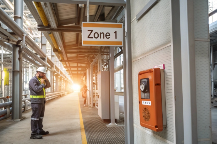
ATEX compliance for explosion-proof telephones means the device marking must match your Zone, gas or dust group, temperature class, and ambient range, and the installation must use approved glands, plugs, and entry methods.

The ATEX compliance checklist for hazardous-area phones?
ATEX is a product rule and an installation rule
ATEX work starts with the phone certificate, but it ends with how the phone is installed. Many teams focus on “Zone 1 phone” and forget the entry hardware, gland type, and sealing method. That is where nonconformities happen. The phone can be correct on paper and still be wrong on site.
A safe approach uses three matching steps:
1) Match the site classification 1 (Zone and gas/dust) to the equipment category and Ex marking.
2) Match temperature limits (T-code or dust surface temperature) to the process hazard and local ambient.
3) Match accessories and entries (glands, stopping plugs, threads, cable types) to the protection concept, while keeping IP and impact performance intact.
ATEX marking is not only a stamp. It is a compact sentence. It tells the protection concept (Ex d, Ex e, Ex ib), the group (surface or mining), the gas or dust subgroup (IIC, IIIC), the temperature class, and the ambient range. When the site changes one element, the phone can become non-compliant even if it still “works.”
A practical checklist keeps the project simple:
| Decision item | What to match | Why it matters |
|---|---|---|
| Hazard zone | Zone 1/2 or 21/22 | Controls where the phone can be installed |
| Protection concept | Ex d / Ex e / Ex ib (or combinations) | Controls gland type, wiring method, and maintenance rules |
| Gas/dust group | IIA/IIB/IIC or IIIA/IIIB/IIIC | Controls ignition risk limits and allowed use |
| Temperature | T4–T6 (gas) or max surface temp (dust) | Prevents hot surface ignition |
| Ambient range | Ta min/max | Ensures marking stays valid in real weather |
| Accessories | Glands, plugs, adapters | Installation can void compliance if mismatched |
A simple buyer rule that prevents most mistakes
When the end user gives a hazardous area dossier, the phone selection should be done by copying key lines into the purchase spec. This keeps engineering and procurement aligned. It also helps the installer because the entry hardware list is clear from the start.
The next sections break this down in a clean way: directives and categories, how to read markings, which documents are mandatory, and how accessories must match to keep the installation compliant.
If this sounds strict, it is strict for a reason. A hazardous-area phone is part of the safety system. The compliance path must be repeatable and easy to audit.
Now let’s go step by step.
A correct ATEX phone is not only certified. It is also installed in a certified way.
Which directives and categories apply—ATEX 2014/34/EU, Category 1/2/3, and Equipment Groups I/II/III?
A project can fail at tender stage if the wrong directive language is used. That mistake forces re-approval and delays commissioning.
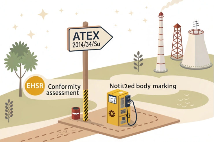
ATEX 2014/34/EU 2 applies to equipment for explosive atmospheres in the EU, with Categories 1/2/3 and Equipment Groups that define where the telephone can be used and how conformity is assessed.
What ATEX 2014/34/EU controls
ATEX 2014/34/EU is the EU directive for equipment and protective systems intended for use in potentially explosive atmospheres. For explosion-proof telephones, it covers the design, assessment, manufacturing control, marking, and documentation needed to place the product on the EU market.
A common misunderstanding is “ATEX equals Zone.” ATEX sets the equipment category and the required conformity assessment route. The Zone mapping comes from the category plus the marking.
Categories and where they fit
For surface industries (Equipment Group II), the common category logic is:
-
Category 1: very high level of protection (often used for Zone 0 or Zone 20)
-
Category 2: high level of protection (often used for Zone 1 or Zone 21)
-
Category 3: normal level of protection (often used for Zone 2 or Zone 22)
For mining (Equipment Group I), the category language usually appears as M1 and M2, and it follows mining-specific risk logic.
About “Equipment Groups I/II/III”
In ATEX directive terms, equipment groups are mainly Group I (mines) and Group II (surface industries). Many engineers also talk about “Group III” when discussing dust in IEC language. In practice, dust is handled inside Group II ATEX equipment, and dust suitability is shown by the “D” category and dust group marking such as IIIC.
How to read ATEX markings—Ex d/e/ib, Zone 1/2 or 21/22, gas/dust groups, T-code, and ambient range?
Many installers see “Ex” and stop reading. That is how mismatches slip into a project and show up during inspection.
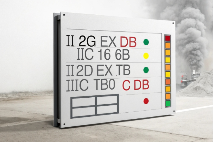
Read ATEX markings like a checklist: protection concept (Ex d/e/ib), equipment group and category (II 2G/2D), gas or dust subgroup (IIC/IIIC), temperature (T-code or °C), and the Ta ambient range.
Break the marking into small pieces
A typical marking line for a hazardous-area telephone can look like this (examples vary by model):
-
II 2G Ex db IIC T6 Gb
-
II 2D Ex tb IIIC T85°C Db
-
Ta -40°C to +70°C
Each block has meaning:
-
“II” means surface industries (not mining).
-
“2G” and “2D” show the category for gas and dust.
-
“Ex db” points to flameproof enclosure protection 3 (often called Ex d).
-
“Ex eb” points to increased safety (Ex e).
-
“Ex ib” points to intrinsically safe circuits (Ex i).
-
“IIC” is the gas group, often the most demanding of the common groups.
-
“IIIC” is conductive dust group 4, often the most demanding dust group.
-
“T6” is the gas temperature class. A lower number like T4 allows a higher maximum surface temperature than T6.
-
“T85°C” for dust is a direct maximum surface temperature marking.
-
“Ta” is the ambient temperature range where the marking is valid.
What documentation is mandatory—EU Declaration of Conformity, Notified Body certificate, technical file, and QA/QC audits?
A phone can be technically correct and still get rejected if the compliance file is incomplete. That often happens at FAT or at the first site audit.
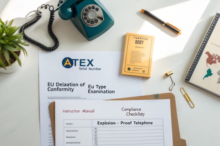
Mandatory ATEX documentation usually includes an EU Declaration of Conformity 5, the relevant Notified Body certificate 6 for higher categories, access to the technical file content on request, and proof of controlled production through QA audits.
The document set that procurement should always request
For a professional ATEX purchase, the baseline document set should include:
-
EU Declaration of Conformity (EU DoC)
-
Certificate details for the ATEX approval (often EU-type examination certificate when a Notified Body is involved)
-
Marking information and label photos that match the certificate
-
Installation instructions with entry methods, gland requirements, and torque notes
-
Operating instructions with safe maintenance warnings
The EU DoC is the formal statement that the manufacturer takes responsibility for conformity. It must identify the product, the directive, and applicable standards.
Do accessories require matching ATEX approvals—cable glands, stopping plugs, threads, and IP/IK ratings for compliant installation?
Many nonconformities come from accessories, not from the phone body. A wrong gland can break Ex integrity and sealing at the same time.
Yes. Accessories must match the protection concept and the certified entry method: cable glands and stopping plugs must be ATEX approved for the same Ex type and zone, threads must match, and the final build must maintain required IP66/67 sealing 7 and mechanical protection.
Cable glands must match the Ex protection concept
A simple rule keeps installers safe:
-
If the entry is Ex d (flameproof), use an Ex d certified gland method approved for that type of cable and entry.
-
If the entry is Ex e (increased safety), use an Ex e certified gland and follow Ex e termination rules.
-
If the circuit is Ex i, the barrier and wiring method must follow Ex i rules, and the entry hardware must still match the enclosure requirements.
Some Ex d installations require barrier glands or compound sealing depending on cable type and construction. This is not a place to guess. The manual and certificate conditions should be followed exactly.
Stopping plugs and adapters are not “just metal”
Stopping plugs must be certified for the same protection concept as the entry. Thread adapters can be allowed only when they are approved for the protection concept and the enclosure design. Many site issues come from mixing thread forms or using non-certified reducers. That can damage threads and reduce sealing integrity.
Conclusion
ATEX compliance needs correct category and marking, complete documentation, and certified accessories. When entry hardware and IP protection match the zone, the installation becomes safe, repeatable, and audit-ready.
Footnotes
-
Overview of how site classifications define the safety protocols for hazardous industrial zones. ↩ ↩
-
Official directive regulating equipment and protective systems intended for use in potentially explosive atmospheres. ↩ ↩
-
Technical explanation of how enclosures contain internal explosions to prevent ignition of surrounding gases. ↩ ↩
-
Safety guidelines for managing risks associated with conductive dust in industrial and grain facilities. ↩ ↩
-
Comprehensive guide to the legal document where manufacturers declare a product’s compliance with EU standards. ↩ ↩
-
Detailed information on the role of independent organizations in assessing high-risk equipment conformity. ↩ ↩
-
Explanation of the ingress protection code system for measuring resistance against dust and water. ↩ ↩


