A weatherproof phone can survive rain and heat, then fail from one angry tug. A torn cord or cracked strain relief can turn a “sealed” unit into downtime.
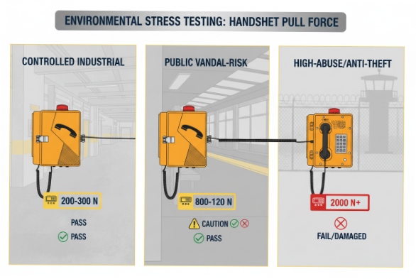
There is no single global “one number” for handset pull strength. In practice, set targets by site risk: about 200–300 N for controlled industrial areas, 800–1200 N for public vandal-risk sites, and 2000 N+ for high-abuse or anti-theft deployments, with clear pass/fail rules.

Handset pull strength is a system requirement, not just a cord number
Handset pull strength looks like a simple question, but the field failure is rarely “the cord broke in the middle.” The real failure path is usually the strain relief, the internal cord clamp, the handset exit grommet, or the mounting point that takes the load when someone yanks the handset. When that load path fails, two bad things happen at the same time. First, the call fails or becomes noisy from broken conductors. Second, the sealing stack is damaged. That is where IP66 dies. Water tracks down the cord. Salt sits in the damaged joint. Sand works into the gap. Then the phone starts to fail slowly, and maintenance becomes a cycle.
In my work, the best results come from writing a pull requirement as a “package test.” The package includes the handset, the cord, the strain relief, the internal anchoring, and the housing mounting points. It also includes what “pass” means after the pull. A pull test that ends with “cord did not detach” is not enough. The unit must still hang up correctly, still dial, and still seal. That last part is often forgotten.
A practical spec uses two load cases:
-
Static pull to simulate a steady tug or someone leaning on the handset.
-
Dynamic pull to simulate quick jerks, like repeated yanks during misuse.
A third check helps a lot:
- Torsion because real abuse is not a straight line. People twist and swing the handset.
A short personal note belongs here. A few years ago, a site team reported “random audio dropouts” on an outdoor help phone. The housing passed water tests in the factory. The root cause was a loose internal clamp. The cord did not break, but the conductors rubbed and cracked at the strain relief. The best fix was not a thicker cord. The fix was a better load path and a tighter pull test in qualification.
Below is a simple way to set targets without overthinking it.
Recommended pull targets by deployment risk
| Deployment type | Static pull target (typical) | Dynamic pull target (typical) | Why this level is used |
|---|---|---|---|
| Controlled industrial (low vandal) | 200–300 N for 60 s | 100–150 N, 50–100 cycles | Handles accidental tugs and rough handling |
| Public access (vandal-risk) | 800–1200 N for 60 s | 300–500 N, 50–100 cycles | Matches deliberate yanks and repeated abuse |
| High-abuse / anti-theft | 2000 N+ for 60 s (or ultimate proof) | 800–1200 N, 50–100 cycles | Targets “pull to steal” behavior |
These are practical procurement numbers. A customer spec can be higher. A correctional application can be higher again. The key is consistency. A phone that is sold as “vandal resistant” should not be tested like a light-duty office device.
Before moving into each test detail, one more rule matters: test the unit after environmental aging when the site is harsh. UV and salt do not only change color. They can harden grommets and make polymers crack. So a pull requirement should also define whether testing is done on fresh samples only, or on aged samples too.
Now the details.
How many newtons should the handset withstand in static and dynamic pull tests?
A handset can feel strong by hand, but real loads come fast and in bad angles. If the spec only says “strong cord,” field abuse will find the weakest point.
Use two pull tests. For most weatherproof phones, aim around 200–300 N static and 100–150 N dynamic in controlled sites. For public sites, move to about 800–1200 N static and 300–500 N dynamic, and confirm the phone still seals and functions after the test.
Static pull: what it simulates and how to run it
Static pull is a steady load. It simulates someone pulling the handset and holding the load, or someone tripping and yanking the handset on the way down. The test setup should mount the phone to a rigid plate using the intended fasteners. Then a force is applied to the handset or cord in the worst realistic direction. For many designs, the worst direction is not straight out. It is down and outward, because that pries the cord exit and strains the clamp.
A useful static test method is:
-
Raise force smoothly to the target in 5–10 seconds.
-
Hold at target for 60 seconds.
-
Release and inspect.
The pass criteria should include:
-
No cord detachment.
-
No conductor damage (continuity check).
-
No cracks in strain relief parts.
-
No change in handset hook operation.
-
Door and gasket line still close correctly.
Dynamic pull: what it simulates and how to run it
Dynamic pull is repeated “jerk” loading. It simulates someone yanking the handset repeatedly, or the handset swinging and stopping suddenly. A good dynamic test uses quick pulls with a defined number of cycles. Many teams use 50–100 cycles. The force can be lower than static, but the repetition finds weak clamp designs fast.
A simple dynamic method is:
-
Apply the force for 1 second.
-
Release for 1 second.
-
Repeat for 50–100 cycles.
Choose numbers by risk, not by hope
The reason public-access phones use higher pull targets is simple. Real vandal behavior is not polite. Some anti-vandal handset assemblies in the market claim very high pull resistance on the lanyard and cord assembly. That shows what buyers expect when theft risk is real.
| Test item | Controlled industrial target | Public vandal-risk target | High-abuse target |
|---|---|---|---|
| Static pull (60 s) | 200–300 N | 800–1200 N 1 | 2000 N+ |
| Dynamic pull | 100–150 N, 50–100 cycles | 300–500 N, 50–100 cycles | 800–1200 N, 50–100 cycles |
| After-test checks | Function + visual | Function + sealing checks | Function + sealing + mounting checks |
A pull number is only useful when it is paired with the post-test checks. That is how the requirement protects IP66, not just the cord.
What tensile rating is required for the curly or armored cord and strain relief?
A strong cord can still fail at the ends. That is where bending, water, and salt attack. A good tensile target must cover the whole cord assembly and the strain relief stack.
Specify tensile performance for the complete cord assembly, not only the inner wires. For curly cords, set an assembly pull target that is at least 2× the maximum dynamic pull. For armored cords, require a reinforced load path, and treat the strain relief and internal lanyard as the primary theft barrier.
Curly (coiled) cord: what to specify
Curly cords are common on standard outdoor phones because they retract and keep the handset tidy. The weak point is the coil ends. The coil wants to stretch under load, and the transition zone wants to kink. A practical spec for curly cords should cover:
-
Jacket material that resists UV and ozone.
-
Cold flexibility 2 if the site is below freezing.
-
A bend protection boot that does not crack.
-
A strain relief that clamps the jacket, not the conductor.
For tensile, the assembly should survive the chosen pull tests with no damage. A good procurement rule is “design margin.” If the dynamic pull requirement is 150 N, the cord and strain relief should not be near failure at 150 N. It should have margin. In practice, a target of 2× dynamic pull as a minimum margin is a clean starting point.
Armored cord: what to specify
Armored cords are used in vandal-prone sites. They often use stainless steel armor 3 with inner conductors. Many anti-vandal designs also add an internal steel lanyard. The lanyard is important because it carries load if the armor is cut or if the conductors stretch.
For armored cords, the spec should include:
-
Armor material (stainless) and construction type.
-
Inner conductor insulation (heat and abrasion resistance).
-
An internal lanyard or tether that anchors to a metal structure, not a PCB.
-
A sealed grommet at the handset and at the panel entry to preserve IP.
Strain relief: what “good” looks like
Strain relief should clamp the jacket and transfer force to the housing structure. It should not rely on glue alone. It should not rely on a sharp edge. It should avoid a design where the cord can saw back and forth during dynamic pulls.
| Component | What to require | What to avoid |
|---|---|---|
| Curly cord | UV-resistant jacket, booted ends, assembly strength margin | Thin boots that crack in sun |
| Armored cord | Stainless armor + secure panel block | Armor ends that can loosen |
| Strain relief | Clamp on jacket + secondary retention | Knotting or informal tying |
| Internal anchoring | Metal bracket or cord block | Load transferred to PCB or small plastic tabs |
| Sealing at entry | Grommet + compression fit | Open gaps around armor or boot |
When the cord and strain relief are specified as a complete assembly, pull strength becomes repeatable in production.
Which standards verify handset and cord pull strength—IEC 60068-2-21 or other vendor methods?
Many buyers ask for a single standard name. In reality, handset pull testing is often verified by a mix of product safety rules and vendor methods, because handset cords are not always covered by one universal clause.
IEC 60068-2-21 is mainly used for component termination strength, not full handset cord retention. For handset and cord pull strength, many projects use vendor methods that borrow pull-cycle concepts from broader safety standards, and they document the fixture, force, time, cycles, and pass criteria clearly.
Where IEC 60068-2-21 fits and where it does not
IEC 60068-2-21 4 is commonly referenced for pull and bend tests on component leads and terminations. It can be useful for internal solder joints, crimp terminals, and cable termination checks inside a phone. It is not a complete answer for a handset pull test, because the handset pull failure is usually mechanical and structural, not only a lead pull-off issue.
So, a practical approach is:
-
Use IEC 60068-style thinking for internal termination checks.
-
Use a vendor-defined “handset retention test” for the full assembly.
What a good vendor method should include
A vendor method becomes credible when it is repeatable and audit-friendly. It should define:
-
Mounting substrate (rigid plate, correct screws, correct torque).
-
Pull direction(s) and the worst-case angle.
-
Static load target and hold time.
-
Dynamic load target, cycle count, and cycle timing.
-
Torsion or swing if required.
-
Electrical continuity checks before and after.
-
IP sealing check after test (at least a focused water spray check at the cord entry).
The test report should include photos of the fixture and the damage criteria. It should also state the sample conditioning. If the phone is targeted for coastal sites, do a salt exposure before pull testing on at least one validation run. If it is targeted for desert sun, do UV and heat conditioning before pull testing on at least one validation run.
A simple “standard-like” test matrix
This matrix is easy to communicate to integrators and QA teams.
| Test | Purpose | Typical method | Pass/fail focus |
|---|---|---|---|
| Static pull | steady tug load | ramp + hold 60 s | no cracks, no movement, still seals |
| Dynamic pull | repeated jerks | 50–100 cycles | no loosening, no wire breaks |
| Torsion | twisting misuse | twist + hold | no boot tear, no clamp slip |
| Continuity | electrical integrity | ohms and audio check | no intermittent faults |
| Post-test seal check | protect IP66 | targeted spray around entry | no leak paths |
A good standard reference helps, but a clear and repeatable vendor method is what makes handset pull performance real in production.
Do mounting points, tethers, and anti-theft lanyards meet the same pull rating?
A phone can have a strong cord and still fail because the load path ends at a weak bracket. In a real pull event, the handset load does not stop at the strain relief. It travels into the housing and into the wall.
Yes. All load-bearing parts in the handset retention path should meet the same pull rating, and the best practice is to rate the tether and mounting points above the cord pull target, so the cord is never “stronger than the structure.”
Think in load paths
The pull force starts at the handset grip. Then it goes through the cord. Then it goes through the strain relief 5. Then it reaches an internal anchoring point. Then it reaches the housing. Then it reaches the mounting plate and the wall anchors. If any one link is weaker, that link fails first.
For public-area phones, the internal tether is often the real anti-theft feature. A steel lanyard 6 anchored to a metal bracket can prevent handset theft even if the cord is damaged. In that design, the lanyard and its anchoring points should be rated at least as high as the static pull requirement, and often higher. Many teams use a simple rule: tether and anchor strength ≥ 1.5× static pull target. This keeps margin for shock loads.
Mounting points matter for IK and for pull
If the phone rocks on the wall, the handset pull becomes a prying action. That can crack panels and open the seal. So mounting points must be strong and the substrate must be rigid. For a high-pull spec, it helps to use a rear steel mounting plate or a reinforced back box.
-
Use a metal cord block or clamp, not a small plastic tab.
-
Use anti-tamper screws 7 so the cord block cannot be removed easily.
-
Avoid routing the cord over sharp edges.
-
Add a second retention point so one clamp slip does not become a full failure.
-
Inspect after pull test for “micro damage” like boot tearing and gasket disturbance.
| Item in the load path | Recommended strength relationship | Common failure if ignored |
|---|---|---|
| Cord assembly | Meets static/dynamic targets | conductor break or armor slip |
| Strain relief | ≥ cord target | jacket pull-out and seal loss |
| Internal anchor bracket | ≥ 1.5× static target | bracket bend or screw pull-out |
| Tether / lanyard | ≥ static target, often higher | handset theft or housing tear |
| Wall mounting | does not shift under load | rocking, seal damage, cracked panel |
When all these points match, the pull spec becomes meaningful. The phone stays sealed, serviceable, and theft-resistant.
Conclusion
Set handset pull strength by site risk, then rate the cord, strain relief, tether, and mounting as one system. Always verify function and sealing after tensile strength tests 8 and pull-off testing 9.
Footnotes
-
Example of a vandal-resistant armored cord spec, showing high static load capabilities for public use. ↩
-
Explanation of why cable flexibility at low temperatures is critical to prevent jacket cracking. ↩
-
Describes the construction and benefits of stainless steel armored cables for protection against vandalism. ↩
-
The IEC 60068-2-21 standard details tests for the robustness of terminations and integral mounting devices. ↩
-
Overview of strain relief bushings and their role in protecting cables from pull and twist forces. ↩
-
Information on wire rope lanyards used for security tethers and retaining components. ↩
-
Discusses high-security screws designed to prevent unauthorized removal of critical components. ↩
-
A general guide to tensile testing methods used to determine the breaking strength of materials. ↩
-
Describes pull-off testing methods, often used for coatings but applicable in concept to adhesion and anchoring. ↩


