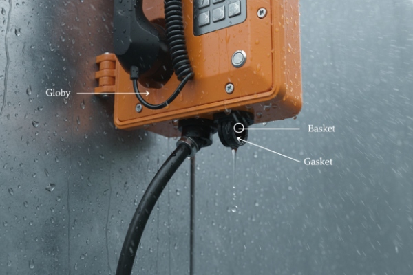
A weatherproof telephone can pass every lab test and still leak in the field if the wrong cable gland is chosen or installed badly.
To select waterproof cable glands for weatherproof telephones, match material to the environment, thread to the enclosure, clamping range to cable OD, and use EMC, strain-relief, or Ex-rated types when the site or standard demands it.

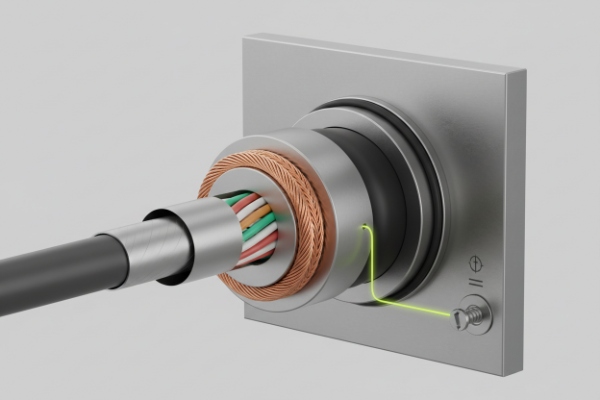
The cable entry is usually the weakest point of a weatherproof telephone. When the gland is correct, the IP66/IP67 rating is real, not just a line on a datasheet. So I always start with environment, thread, and cable size before talking part numbers.
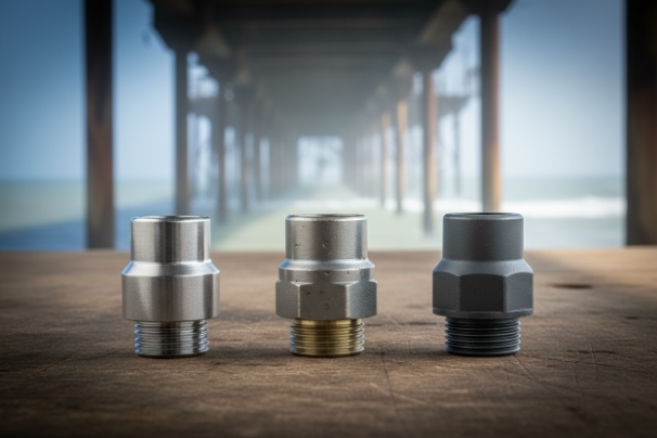
Which gland materials fit coastal and chemical sites—316L, nickel-plated brass, or polyamide?
Salt, UV, and chemicals can destroy a cheap gland long before the telephone housing shows any damage.
For coastal and chemical sites, use 316L stainless or good nickel-plated brass cable glands, and keep polyamide for lighter, cleaner outdoor locations where UV and chemicals are less aggressive.
How I match gland material to the environment
For a weatherproof telephone, the housing is only half the story. If the gland corrodes, cracks, or goes chalky, water will find its way in around the cable. So I treat the gland material as a key part of the environmental design.
1. Polyamide (PA / nylon) glands
Polyamide glands 1 work well in many general outdoor and indoor sites:
- Light, easy to install, and cost-effective
- UV-stabilized versions handle sun exposure much better than basic PA
- Good for standard building exteriors, factories, and commercial areas with low chemical risk
Where I avoid basic polyamide:
- Coastal sites with heavy salt-fog
- Chemical plants where solvent mist or oils are present
- High-temperature zones where the plastic can soften or creep
2. Nickel-plated brass glands
Nickel-plated brass 2 is a very useful middle ground:
- Strong metal body with good mechanical strength
- Nickel plating gives good corrosion resistance for many industrial environments
- Good choice for refineries, heavy industry, and general outdoor cabinets
Things to watch:
- In very harsh marine environments, the plating can wear or pit over many years
- If mounted in raw aluminum without proper isolation, galvanic effects can show up
3. 316L stainless steel glands
For serious coastal and marine work, I like to move straight to 316L:
- Excellent corrosion resistance in salt-fog and marine spray
- Strong mechanical strength and stable performance over long service life
- Ideal for harbor telephones, offshore platforms, and chemical splash zones
The cost is higher, but in high-salt or high-chemical locations, the extra life often pays back in fewer site visits and replacements.
| Environment type | Recommended gland material | Notes |
|---|---|---|
| General indoor / light outdoor | UV-stabilized polyamide | Check UV rating and temperature range |
| Industrial plant / refinery | Nickel-plated brass | Good mix of strength and corrosion resistance |
| Coastal / marine / chemical zone | 316L stainless steel 3 | Best choice for long-term harsh exposure |
Whatever material I pick, I always match the gland’s IP rating to the telephone. If the phone is IP66/IP67 or NEMA 4X, the gland must be at least the same.
Which thread and entry size should be specified—M20/M25 or 1/2″ NPT—and matched to the enclosure?
A perfect gland with the wrong thread is just an expensive plug that never seals right.
Choose M20×1.5 or M25×1.5 for most metric housings, and 1/2″ NPT for North American conduit installs, always matching the gland thread to the enclosure boss and sealing method.
Picking entry size and thread that actually works on site
In weatherproof telephone projects, I see the same pattern: the housing is designed in metric, the site uses NPT, and someone hopes PTFE tape will fix the mismatch. The result is often a slow leak that shows up months later.
So I start with three simple steps:
1. Read the enclosure drawing, not just the spec line
The housing should state the boss type, for example:
- M20×1.5 or M25×1.5 threaded hole
- 1/2″ NPT or 3/4″ NPT entry
- Sometimes a knockout that can be adapted
I always select glands with the exact same thread standard. Metric to metric. NPT to NPT. No “close enough”.
2. Choose the entry size based on cable design
- For a single Cat5e/Cat6 or small multi-core cable, M20 or 1/2″ NPT is enough
- For thicker multi-core cables, combined power/data, or future expansion, M25 or 3/4″ NPT gives more space
If I know the project may add beacons, cameras, or extra I/O later, I prefer to give them a second M20 entry or a larger M25 to keep options open.
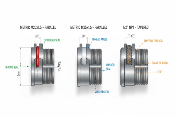
3. Use the right sealing style for each thread
-
Metric (M20/M25):
-
NPT:
- The seal is on the tapered threads, supported by PTFE tape or a thread sealant.
- Over-torque here can crack plastic enclosures or distort thin walls.
| Enclosure boss type | Typical gland choice | Sealing style |
|---|---|---|
| M20×1.5 | M20 cable gland | O-ring or flat sealing washer |
| M25×1.5 | M25 cable gland | O-ring or flat sealing washer |
| 1/2″ NPT | 1/2″ NPT cable gland or hub | Thread sealant / PTFE tape |
By matching the thread exactly, I keep the IP66/IP67 rating realistic and avoid the common “almost fits” that cost time and reputation later.
How do cable OD, clamping range, and seals maintain IP66/IP67 after installation?
Even the best gland will leak if the cable is too small, too large, or pulled at the wrong angle.
IP66/IP67 depends on matching the gland’s clamping range to the cable OD and tightening the seal correctly, so the elastomer grips the jacket all around without crushing it.
Why cable size and seal geometry matter so much
In the lab, the gland manufacturer uses a cable that sits right in the middle of the specified range. On site, people often use whatever cable is available and hope the gasket will adapt. That is where sealing problems start.
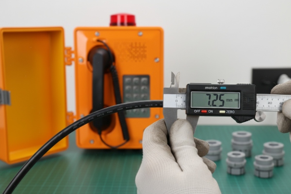
1. Match the gland’s clamping range to the real cable OD
I always measure or confirm the actual cable outer diameter, not just the nominal size in a catalog. Then:
- Pick a gland whose min–max clamping range brackets that OD
- Prefer a range where the cable sits near the middle, not at the extreme limit
If the cable is too small:
- The seal cannot compress enough to grip all around
- Even if the nut is tight, small gaps remain, especially under movement
If the cable is too large:
- The jacket can be cut or over-compressed
- Cracks appear over time and the seal fails under thermal cycling
2. Understand the sealing points
There are usually two separate seals:
-
Cable-to-gland seal
- The elastomer inserts or grommet clamp onto the cable jacket
- This is what stops water traveling along the cable into the housing
-
Gland-to-enclosure seal
- O-ring or flat washer under the gland head for metric/BSP
- Thread sealant for NPT/BSPT
- This blocks water from creeping in around the outside of the gland body
Both must be correct to keep IP66 5 / IP67 6. If one fails, water finds a way.
3. Install for strain relief, not just sealing
If the cable is free to move or be pulled:
- The gland sees bending and tension that slowly damage the seal
- IP66/IP67 may hold at first, but not after months of movement
For exposed or mobile runs, I prefer glands with integrated strain relief or add external clamps so the gland only handles sealing, not mechanical loads.
| Parameter | Good practice | Risk if ignored |
|---|---|---|
| Cable OD | Measure and pick correct range | Loose sealing or damaged cable jacket |
| Clamping torque | Use manufacturer’s torque table | Under-seal or crushed grommets |
| Strain relief | Use SR glands or external clamps | Seal fatigue from repeated flexing |
When the cable OD, clamping range, and seals line up, IP66/IP67 is not just a test result. It stays true in real weather and real use.
Are EMC, strain-relief, or Ex-rated glands required; what approvals and temperature ratings should be checked?
Some sites only need “waterproof”. Others need EMC, anti-pull, or even explosion protection on the same tiny entry point.
For critical sites, specify EMC, strain-relief, or Ex-rated cable glands as needed, and always confirm approvals (IEC/EN, UL, ATEX/IECEx) and working temperature that match the telephone and the cable.
When to go beyond a basic waterproof gland
Once the environmental basics are covered, I ask three more questions: noise, pull, and area classification.
1. EMC (shielded) glands
On SIP and VoIP telephones, Ethernet and audio cables can act as antennas. In sites with high RF or heavy drives:
- Use EMC glands that bond the cable screen to the enclosure
- Ensure the telephone housing has a defined earth point for that screen
- Check that the EMC gland still offers IP66/IP67 and the right material
This is important near:
- Rail traction systems
- Big VFD-controlled motors
- Radio and radar installations
2. Strain-relief glands
If the cable will be:
- Pulled during maintenance
- Shaken by wind
- Moved by doors, gates, or moving machinery
then I specify glands with integrated strain-relief or add external grips. The idea is simple: the seal should not see full cable tension.
For handset cables or exposed runs, this is especially important. A flexible gland tail or armored support often pays for itself in fewer failures.
3. Ex-rated glands and approvals
For hazardous areas (gas, dust, or mines), everything changes. Then it is not enough that a gland is “waterproof”:
- The gland must carry the correct ATEX 7 / IECEx 8 / UL 9 marking to match the telephone
- The type of Ex protection (Ex e, Ex d, Ex t, etc.) must match the enclosure style
- Any reducers, adapters or stopping plugs must be approved as part of the same system
In these cases, I always recommend using exactly the gland types listed in the telephone’s Ex certificate or installation manual, not “equivalent” items.
4. Temperature range
Finally, I check the rated temperature range of:
- The gland body
- The sealing elastomer
- The telephone itself
For desert or very cold climates, it is easy for the gasket material 10 to become too hard or too soft outside a basic -20…+80 °C range. That is why I like to see clear temperature limits on the data sheet.
| Extra requirement | Gland feature needed | Typical checks |
|---|---|---|
| EMC | Shield-bonding / EMC gland | Screen contact, IP rating, material |
| High pull / motion | Strain-relief or flex-protect design | Pull rating, bend protection |
| Hazardous area | Ex-certified gland | Marking, certificate, matching Ex type |
| Extreme climate | Wide temperature elastomer and body | -40…+85 °C or better, UV resistance |
Once these items are clear, the gland specification stops being a guess. It becomes a repeatable part of the project standard.
Conclusion
For reliable weatherproof telephones, treat the cable gland as a critical component: match material, thread, clamping range, and special functions so the entry is never weaker than the enclosure itself.
Footnotes
-
Discusses the benefits of polyamide cable glands, including cost-effectiveness and durability in standard environments. ↩
-
Overview of material compatibility for cable glands, highlighting nickel-plated brass for industrial use. ↩
-
Explains the superior corrosion resistance of 316L stainless steel for marine and harsh chemical environments. ↩
-
A guide to O-rings and sealing washers, crucial for maintaining ingress protection in threaded entries. ↩
-
Defines the IP66 rating, indicating protection against powerful water jets and dust. ↩
-
Defines the IP67 rating, indicating protection against immersion in water up to 1 meter. ↩
-
Introduction to the ATEX directive for equipment used in explosive atmospheres within the EU. ↩
-
Overview of the IECEx system for international certification of equipment for use in explosive atmospheres. ↩
-
Details UL certification services for hazardous locations, relevant for North American markets. ↩
-
Information on sealing materials used in cable glands and their temperature performance characteristics. ↩


