A lightning surge can turn a certified Ex telephone into a dead endpoint. The phone still looks fine, but the port is gone and the SOS point fails during a real event.
Explosion-proof telephones are usually specified with IEC 61000-4-5 surge immunity on power, PoE/Ethernet, and I/O, plus telecom resistibility standards for analog ports. Add SPD coordination rules (IEC 61643 and IEEE C62.41) without breaking ATEX/IECEx installation compliance.

How do surge standards fit together for Ex telephones?
One phone, many surge paths
An Ex telephone has several entry points for surge energy:
-
PoE/Ethernet (data pairs and PoE power)
-
24 VDC power
-
Dry-contact I/O and relay wiring
-
Analog ports (FXS/FXO) if present
-
Shield/drain wires and earth references
Each path needs a test method that matches the line physics. IEC 61000-4-5 1 is the main “system-level” immunity test used across industries. It defines the surge generator waveforms and gives a range of recommended test levels based on installation classes. It also makes a key point: the product standard or the buyer must set the final test levels and the performance criteria for pass/fail.
Telecom standards (ITU-T K-series) are a better match for ports that behave like telecom lines, such as analog subscriber interfaces. Power SPD standards (IEC 61643) and surge environment guidance (IEEE C62.41) help size and coordinate protection devices so tests and field behavior line up.
A strong procurement spec does not list standards only. It ties standards to ports, test modes (common and differential), and a clear “still usable after surge” requirement.
A simple compliance map that works in audits
| Interface on Ex phone | Main test family | Why it fits | What you must write in the spec |
|---|---|---|---|
| PoE/Ethernet | IEC 61000-4-5 (high-speed line guidance) | Covers surge coupling and levels for installed equipment | Common-mode + pair mode, port state, pass criteria |
| 24 VDC power | IEC 61000-4-5 | Covers DC supplies and DC I/O levels by installation class | Line-line and line-earth levels, polarity, repetitions |
| I/O / relays | IEC 61000-4-5 | Covers I/O coupling methods and setup | Coupling method (cap/clamp), level, acceptance |
| Analog FXS/FXO | ITU-T K.21/K.45 2 (as applicable) + IEC 61000-4-5 where needed | Telecom resistibility matches metallic line threats | Which K-rec applies, line type, test profile |
| SPD selection | IEC 61643 + IEEE C62.41 | Aligns field SPDs with expected surge stress | Type staging, Up, Iimp/Imax, coordination notes |
A buyer gets better results when the phone vendor, the SPD vendor, and the integrator use the same map. That stops gaps like “panel SPD is strong but the data port has no test requirement”.
Now the detail that most teams need first: what IEC 61000-4-5 really asks for in waveforms, CDNs, and pass criteria.
Which immunity tests are required—IEC 61000-4-5 levels, test waveform, CDN setup, and performance Criteria A/B/C?
A surge spec fails when it only says “IEC 61000-4-5 compliant”. That line hides the waveform, the coupling method, and the pass criteria.
IEC 61000-4-5 uses combination-wave surge generators (1.2/50 µs voltage and 8/20 µs current, and also 10/700 µs–5/320 µs for some line cases), applies surges through coupling/decoupling networks when practical, and classifies outcomes from normal operation to temporary loss to permanent damage.
Waveforms you must name in the purchase spec
IEC 61000-4-5 defines a combination-wave generator that produces a 1.2/50 µs open-circuit voltage and an 8/20 µs short-circuit current. It also links typical voltage levels (0.5, 1, 2, 4 kV) to peak short-circuit currents (0.25, 0.5, 1, 2 kA) for that generator family. This is the baseline most labs use for industrial electronics.
It also defines a 10/700 µs open-circuit voltage with a 5/320 µs short-circuit current waveform. This family is often used when tests align with telecom-style surge behavior on certain ports.
For Ex telephones 3, the best practice is to state:
-
which waveform family applies to each port type
-
which polarity (positive and negative)
-
how many hits per mode and per polarity
-
whether the phone is powered and in service during the test
CDN setup is not optional detail
If the lab cannot couple the surge in a realistic way, the test becomes weak. IEC 61000-4-5 describes coupling/decoupling networks (CDNs) 4 and also warns that many CDNs cannot handle high-speed communication bandwidth. When no adequate CDN exists for a high-speed data port, the surge may be applied directly at the port. That matters for SIP/PoE Ethernet, because it is far above 100 kHz.
For interconnection and I/O lines, the standard describes coupling methods such as capacitive coupling and coupling using clamping devices or arrestors. Each method changes the real stress seen by the equipment.
Criteria A/B/C should be written as behavior, not letters
In practice, Criteria A/B/C is a buyer-friendly summary of what the phone is allowed to do during and after the surge:
-
A: works as specified during and after
-
B: brief glitch, then self-recovers
-
C: needs operator action to restore
-
D: damage or unrecoverable loss (never acceptable for emergency phones)
IEC 61000-4-5 itself classifies test results from normal performance to temporary loss (with and without operator intervention) and to non-recoverable damage. For emergency phones, the procurement target is usually A or B for voice and SOS functions, and never D.
| Item to specify | What the lab will do | What you should require for Ex phones |
|---|---|---|
| Waveform family | 1.2/50–8/20 and/or 10/700–5/320 | Name which ports use which waveform |
| Coupling modes | Line-line and line-earth modes | Require both common and differential where relevant |
| CDN method | Capacitive, clamp, arrestor, or direct | Require method and document it in test report |
| Pass criteria | Classify function loss and recovery | A or B for SOS/voice, no permanent damage |
| Powered state | Powered and operating | Test in normal call + paging-ready state |
A spec that includes these five items is much harder to game and much easier to compare across vendors.
Next is the telecom question. Many sites have analog ports, and some teams want ITU-T K tests to cover VoIP lines too.
Do telecom standards like ITU-T K.21/K.45 cover SIP/PoE lines and analog FXS/FXO ports?
Teams often assume “telecom standard” means “anything that carries voice”. That is not how the scopes are written.
ITU-T K.21 and K.45 are aimed at telecommunication equipment resistibility on metallic telecom-style interfaces. They fit analog FXS/FXO and similar line interfaces much better than Ethernet SIP/PoE, which is normally specified through IEC 61000-4-5 (including its high-speed line guidance).
Where K.21 and K.45 sit in real projects
K.21 is written for telecommunication equipment installed in a customer premises context and assumes proper earthing and bonding practices. K.45 is written for equipment installed in access and trunk networks, and it references basic resistibility test methods through K.44. These scopes matter when deciding if a test report is “the right evidence” for your port type.
For an Ex telephone:
-
If the phone has an analog line interface that leaves the building or connects to legacy telecom wiring, K.21-style resistibility evidence is useful and often requested.
-
If the phone is pure SIP over Ethernet/PoE, IEC 61000-4-5 is the cleanest baseline because it explicitly treats high-speed communication lines and the coupling limits of CDNs.
SIP/PoE is a communication line, but not a classic K-line
Ethernet ports can be stressed by surges, but the coupling, impedance, and pairing are not the same as a two-wire telecom loop. Also, PoE injects DC power onto the same pairs, so protection and testing must treat both data and power behavior.
This is why a practical approach is:
-
Use IEC 61000-4-5 as the main test language for SIP/PoE ports
-
Use ITU-T K standards mainly for analog ports and for interfaces that behave like telecom line plant
-
If a buyer wants a single “telecom-grade” line of evidence, ask the vendor to provide both: IEC 61000-4-5 for Ethernet and ITU-T K evidence for analog
How to write a clean “port-by-port” requirement
| Port type | Preferred test evidence | What to ask the vendor for |
|---|---|---|
| SIP/PoE RJ45 | IEC 61000-4-5 (high-speed line clause) | Test method when CDN is not practical, levels, modes |
| Analog FXO/FXS | ITU-T K.21 (premises) or K.45 (network) + port details | Metallic line surge profile, pass/fail behavior |
| Dry-contact I/O | IEC 61000-4-5 I/O coupling | Coupling method, levels, and recovery requirement |
This approach stops a common mistake: using a telecom resistibility report to “cover” an Ethernet port without any mention of pairing, coupling, or PoE behavior.
Next is the most useful part for engineering teams: how to specify surge levels and modes for PoE, 24 VDC, and I/O in a way that a lab can repeat.
How to specify surge levels for PoE, 24 VDC, and I/O—common/differential mode, kV/kA, and line pairing?
A surge requirement becomes real only when it is written in a testable format. “Industrial surge protection” is not testable wording.
Specify surge by port, by coupling mode (line-line and line-earth), by waveform family, and by installation class. Use IEC 61000-4-5 Annex A as the baseline level table, then adjust by cable length, exposure, and primary protection staging.
IEC 61000-4-5 provides installation classes (0 to 5) and a table of recommended test levels based on how cables run and how exposed the installation is. In plain language:
-
Class 0–2 are more protected or better separated
-
Class 3–4 include parallel runs and outdoor-like routing
-
Class 5 is very exposed and often needs primary protection assumptions
For many hazardous sites:
-
Indoor refinery units with long parallel trays can behave like class 3
-
Outdoor pipe racks and offshore decks can behave like class 4
-
Very exposed overhead interfaces push toward class 5 thinking
Common mode vs differential mode in phone terms
-
Common mode (line to earth / line to shield): the whole port rises vs ground. This kills PHY chips and I/O inputs.
-
Differential mode (line to line / pair to pair): stress between conductors. This breaks isolation components and front-end protection.
For PoE/Ethernet, pairing must be named:
-
Which pair(s) are surged
-
Whether the surge is applied pair-to-pair (differential) and pair-to-shield/earth (common)
-
Whether PoE is active during the test
Put kV and kA in the spec, but tie them to the waveform
IEC 61000-4-5 links voltage level to a typical short-circuit current for the generator family. That makes kV and kA consistent. A 2 kV level is not “just voltage”. It also implies a current stress when shorted.
A practical spec block for an Ex SIP phone often looks like this:
-
24 VDC input: class 3 or 4, line-line and line-earth levels as applicable
-
I/O: unsymmetrical line-earth levels, and line-line if the I/O is differential
-
Ethernet: apply per high-speed line method, common-mode emphasized, and differential pair mode as defined in the test plan
Example requirement table (buyer-facing)
| Interface | Exposure assumption | Coupling modes | Baseline levels to call out |
|---|---|---|---|
| 24 VDC power | Class 3 indoor trays | L-L and L-E | 1 kV (L-L) and 2 kV (L-E) baseline idea |
| I/O (dry contact) | Long field wiring | L-E mainly | 2 kV common-mode baseline idea |
| PoE/Ethernet | High-speed port | Pair modes + common-mode | 2 kV common-mode target for exposed runs, documented method |
| Shielded lines | Shield bonded | “all lines to ground” | Use shielded line guidance, allow level reduction for short runs |
Cable length matters. IEC 61000-4-5 allows lower levels for shorter cables in some cases and even advises no test at data connections intended for very short cables. A realistic plant spec should still test critical emergency phones, but it should be honest about cable lengths and routes, because the lab setup must match reality.
Now the last big topic: SPDs and coordination. Many projects add staged SPDs, but the Ex rules and the test evidence must still match.
Must surge protection coordination follow IEC 61643 and IEEE C62.41 while maintaining ATEX/IECEx compliance?
Some teams treat EMC tests and SPDs as separate workstreams. That creates gaps. A phone can pass a lab test and still die in the field if SPDs are mismatched or grounding is weak.
Yes. Coordinate surge protection using IEC 61643 (SPD classification and parameters) and IEEE C62.41 guidance (surge environment and test waveforms for LV power circuits), and apply them without changing the certified Ex protection concept of the installation.
Coordination is about “who clamps first” and “who survives”
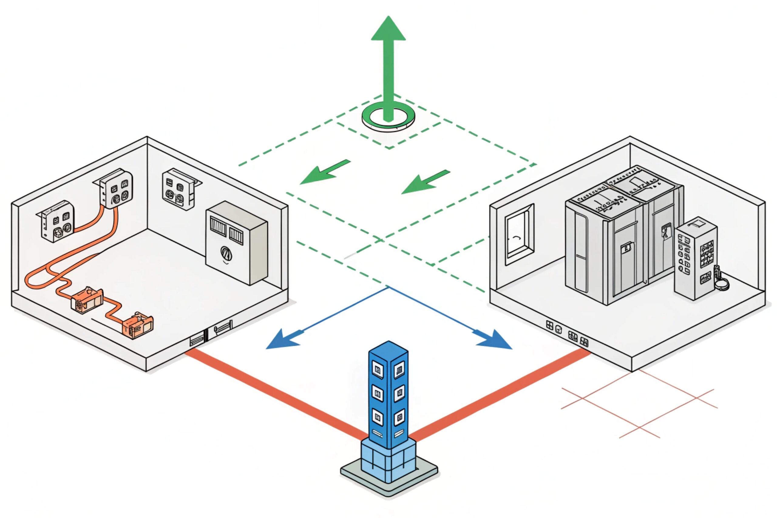
A staged SPD 5 design often includes:
-
A stronger device at the building or panel entry (high energy)
-
A distribution SPD closer to the PoE switch or DC supply
-
A fine clamp near the phone (low let-through)
IEC 61643 6 is used to select and describe SPDs for low-voltage systems. IEEE C62.41 documents the surge environment and uses representative waveforms and locations so engineers can match protection to likely stress.
For Ex telephones, coordination must also consider functional behavior:
-
PoE must still negotiate correctly
-
SIP must still register after a surge
-
I/O must not latch up
-
Paging must still work
A coordinated design also matches what the lab test represents. If the lab test assumes “primary protection present” at higher installation classes, the site must actually install that primary protection. If not, the test report and the field reality do not match.
ATEX/IECEx compliance must not be “fixed later”
Surge protection hardware and wiring changes can affect compliance if they touch the certified enclosure, glands, or protection concept. In projects, the safest approach is:
-
Keep high-energy SPDs in safe-area panels or certified field cabinets as per site practice
-
Use certified glands and maintain correct sealing and bonding
-
Avoid adding non-certified components inside Ex d flamepath enclosures
-
If a device-side protector is needed in Zone 1/2, select a solution that is suitable for that area and install it in a compliant way
Write the coordination requirement as a deliverable
| Coordination deliverable | What it proves | What you should require |
|---|---|---|
| SPD staging diagram | No single point takes full energy | Panel + distribution + device stage shown |
| Parameter list | Clamping and energy handling match | Up, Iimp/Imax, Uc, and coordination notes |
| Grounding/bonding plan | SPDs have a real reference | Bond paths, bar locations, cable shields |
| Test evidence alignment | Lab assumptions match site build | “Primary protection present” is verified |
| Ex compliance statement | No change to protection concept | Glands, boxes, and mounting remain compliant |
In DJSlink projects, the most reliable outcome comes from treating surge work as part of the voice system design, not as an accessory. A surge plan that includes test levels, SPD staging, and grounding checks will keep emergency phones online for years, not just on commissioning day 7.
Conclusion
Use IEC 61000-4-5 as the core surge test language, add ITU-T K evidence for analog ports, and coordinate SPDs with IEC 61643 and IEEE C62.41 while keeping Ex installation rules intact.
Footnotes
-
Standard specifying test waveforms and immunity levels for equipment against surge voltages. [↩] ↩
-
ITU-T recommendations defining resistibility requirements for telecommunication equipment to overvoltages and overcurrents. [↩] ↩
-
Hazardous area telephone designed to operate safely in environments with explosive risks. [↩] ↩
-
Specialized networks used in testing to couple surge pulses to EUT lines while decoupling them from auxiliary equipment. [↩] ↩
-
Surge Protection Device designed to limit transient overvoltages and divert surge currents. [↩] ↩
-
International standard for low-voltage surge protective devices connected to power systems. [↩] ↩
-
Comprehensive strategy ensuring electrical protection aligns with safety certification and operational reliability. [↩] ↩


