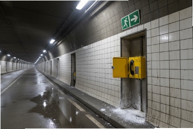
A tunnel incident gives no second chances. Smoke, noise, and panic can turn a normal help point into a dead end if the phone fails.
Yes. Explosion-proof telephones can be used in tunnels when the risk study matches the right Zone rating, IP/IK durability, tunnel EMC and fire rules, and the SIP network is built for long-distance uptime and clear emergency workflows.

A tunnel-ready checklist that keeps safety, compliance, and uptime aligned
Tunnel projects often mix three worlds. The first world is hazardous-area safety. The second world is transport standards and tunnel authority rules. The third world is day-to-day maintenance reality. A phone that passes lab checks can still fail the tunnel inspection if the EMC file is wrong. A phone that is compliant can still fail operations if the network has micro-outages. A phone that works today can still fail next year if corrosion and cable retention are weak.
From my side, a tunnel design works best when it is built like a system, not like a single device purchase. The device spec should include the local risk profile, the tunnel type, and the operating mode. Road tunnels focus on smoke, fire systems, and traffic control alarms. Rail tunnels focus on traction power noise and signaling integrity. Utility tunnels may focus on gas, dust, and chemical splash.
Start with a risk-driven device class
Many tunnels are not classified as hazardous areas. Still, some tunnels have fuel vapor risk, solvent storage risk, or cable galleries with gases. Some tunnel zones can be Zone 2 in special areas. In those cases, an Ex-rated 1 telephone becomes relevant. When the tunnel has no hazardous classification, a heavy-duty IP66/IK10 industrial telephone can be enough.
Match phone features to tunnel operations
Tunnel operators care about a few things:
- The call must connect fast.
- The voice must be clear at high noise levels.
- The help point must show status and location.
- The system must survive washdown, dust, and vibration.
- Maintenance must be simple and safe.
Use one table to avoid “spec drift”
| Tunnel requirement | What to specify on the telephone | What to specify on the system side |
|---|---|---|
| Safety compliance | ATEX 2 Zone rating only if needed | Location-based risk assessment |
| Durability | IP66/IP67, IK10, corrosion-resistant build | Inspection plan and spare parts |
| EMC compatibility | Rail or road tunnel EMC rules | Network grounding and cable routing |
| Emergency workflow | Hotline, auto-dial, beacon relay | PBX routing, alarm escalation |
| Long-distance uptime | PoE stability, surge defense | Fiber rings, redundant SIP proxies |
A tunnel spec becomes easy when this checklist is agreed early. The next section explains how standards fit tunnels and how to pick the right set without overbuying or missing a critical rule.
Now it is time to map the tunnel type to the correct standards and authority expectations.
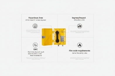
Which standards fit tunnels—ATEX Zone 2, IP66/IP67, IK10, EN 50121-4 EMC, or NFPA 502 fire?
Tunnels attract “standard overload.” One team asks for rail EMC. Another team asks for fire rules. Then the device ends up over-specified and still missing one required document.
A tunnel telephone standard set should be chosen from the tunnel risk type and the authority scope. The goal is simple: meet what the tunnel owner must enforce, and avoid mixing unrelated standards in a way that slows approval.
Road tunnels: focus on fire, smoke, and emergency systems
Road tunnels often reference tunnel fire safety rules and emergency communication rules from local authorities. NFPA 502 3 is a well-known fire and life safety standard for road tunnels and bridges in many projects. Still, local rules can be stricter or different. The phone should support the tunnel’s emergency communication plan. This often means clear signage, hotline calling, and alarm outputs to tunnel control.
Rail tunnels: focus on EMC and traction power noise
Rail environments can be harsh for EMC. Traction power systems and signaling can create noise that upsets weak designs. EN 50121-4 4 is commonly referenced for signaling and telecom EMC in railway environments. In a tunnel, this matters because long cable runs act like antennas, and switch rooms can sit near high-power equipment.
ATEX Zone 2: only when the tunnel is actually classified
ATEX Zone 2 requirements apply only when the tunnel or a part of it is classified as hazardous. It is not a default tunnel rule. If Zone 2 is defined, then the phone must match the required gas group and temperature class, and cable entries must follow the certified configuration.
IP and IK: the daily survival layer
IP66/IP67 5 and IK10 6 are practical tunnel targets because tunnels get water, dust, and impacts. Road tunnels can see vehicle spray and washdown. Rail tunnels can see dust and condensation. The phone should survive that without a “special cover” that maintenance forgets to close.
| Tunnel type | “Must check” standards set | “Nice to have” support | Common mistake |
|---|---|---|---|
| Road tunnel | Fire and emergency comms rules, IP/IK | Corrosion class statement | Treating any IP phone as tunnel-ready |
| Rail tunnel | Rail EMC rule set, IP/IK | Redundant network design notes | Ignoring EMC and grounding |
| Classified tunnel zone | ATEX/IECEx + IP/IK | Certified gland set | Using adapters and glands without control |
A tunnel project moves faster when standards are written as a small, correct list. The next step is integration. Tunnel phones are rarely standalone. They must work with PA/GA, SOS call boxes, CCTV, and alarms.
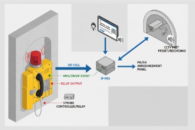
How do these phones integrate with tunnel PA/GA, SOS call boxes, CCTV, and alarms?
A tunnel control room needs one screen and one workflow. If the phone is separate, operators lose time and mistakes happen.
Tunnel telephones integrate best when the system uses a clear SIP call plan, multicast paging support for PA/GA behavior, ONVIF or event linkage for CCTV pop-up, and relay I/O for alarms and beacons. The goal is to make one help point trigger the right actions automatically.
SIP call flows: simple and location-aware
In many tunnel projects, each help point uses a hotline to the tunnel control room. The call should send a clear location label. That label should match the tunnel’s section naming. A good naming format is short and consistent, like “RT-01-NE-200m” or “Rail-Tunnel-A-Bay-12.”
A second call route is also useful. When the control room is busy or unreachable, the call can fail over to a backup desk or a duty mobile group.
PA/GA: multicast paging or gateway routing
Tunnel PA/GA systems often use dedicated amplifiers and speakers. SIP endpoints can connect in two common ways:
- Multicast paging 7 groups for one-to-many announcements when the PA system supports it.
- SIP-to-PA gateways that inject audio into the amplifier system.
In practice, multicast works well for fast area paging. Gateways work well when the PA/GA is an analog amplifier network.
CCTV linkage: ONVIF and event-driven video pop-up
Tunnel operations often rely on “call + camera.” When someone lifts the handset or presses SOS, the nearest CCTV view should pop up. ONVIF 8 event linkage is a common way to connect devices and video systems. Even when ONVIF is not used directly by the phone, the phone can send events to a platform that triggers camera pop-up.
Alarms and beacons: relay I/O keeps it simple
Relay outputs are still the most reliable bridge to alarms:
- A relay can trigger a strobe beacon on the call box or the tunnel wall.
- A relay can signal a PLC input so SCADA shows “help point active.”
- An input can trigger auto-dial when a local emergency push button is pressed.
| Integration target | Interface | What it enables | Practical design rule |
|---|---|---|---|
| Control room calling | SIP 9 PBX | Hotline, group ring, location ID | Keep call steps under 2 actions |
| Tunnel paging | Multicast or gateway | Area announcements | Separate paging from normal voice queues |
| CCTV pop-up | ONVIF or event API | Faster situational awareness | Trigger by call state, not by manual steps |
| Alarms | Relay output + strobe | Visible help point activation | Latch alarm until operator acknowledges |
Integration is only as reliable as the network and power that carry it. Tunnels are long. Tunnels also have hard-to-reach cabinets. The next section covers the network and power design that keeps SIP and RTP stable over distance.
What network and power design suits long tunnels—fiber rings, industrial PoE switches, PoE extenders, QoS, and redundant SIP proxies?
A tunnel network is not a normal campus network. Distance is long. Access is limited. A single weak switch can create a blind zone for hours.
A stable tunnel VoIP design uses fiber as the backbone, ring or dual-homing for redundancy, industrial PoE switches in protected cabinets, careful use of PoE extenders, strict QoS for SIP/RTP, and redundant SIP proxies so calls survive server or path failure.
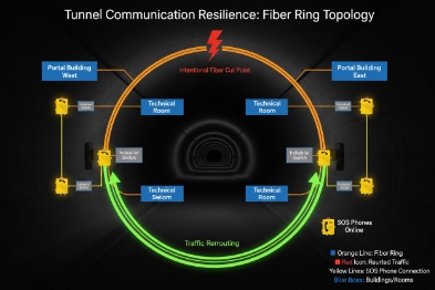
Fiber rings: the backbone that tolerates cable damage
Copper Ethernet does not like long distances in tunnels. Fiber is the right backbone for long runs. A ring topology helps keep service when one segment is cut. In tunnels, cable damage is not rare. Vehicles, maintenance tools, and water events can cause damage. A ring or dual path reduces outage scope.
Industrial PoE switches: match the environment, not just the bandwidth
Tunnel cabinets see humidity and temperature swings. Industrial PoE 10 switches with good ingress protection and proper grounding points reduce random failures. PoE budget must include worst-case draw, not average. Cold start currents, ringers, and beacon loads can push peaks. A tight PoE budget can cause resets that look like “network loss.”
PoE extenders: use them carefully and document them
PoE extenders help where a cabinet cannot be added. Still, each extender adds risk. It adds another device and another failure point. In many projects, a better option is to place another small PoE switch node with fiber uplink. If extenders are used, they should be easy to access, labeled, and monitored.
QoS for SIP/RTP: prevent video and SCADA from stealing voice
Tunnel networks carry CCTV streams and control traffic. Voice needs priority:
- Mark RTP with DSCP EF when possible.
- Keep SIP signaling in a stable class.
- Map DSCP to 802.1p inside the LAN.
- Use strict priority queues on uplinks, with policing to prevent abuse.
Redundant SIP proxies: keep calls working during failures
A tunnel voice system should not have a single SIP server path. Two proxies or two call servers are common. The phones should support primary and secondary registration and fast failover without repeated flapping.
| Network element | Best tunnel choice | Why it works in tunnels | What to monitor |
|---|---|---|---|
| Backbone | Fiber ring or dual path | Long distance and cut tolerance | Ring status and link loss events |
| Access | Industrial PoE switch nodes | Better endurance in cabinets | PoE power, port errors, temperature |
| Voice priority | QoS with voice VLAN | Prevents congestion loss | Queue drops, DSCP trust stats |
| Call control | Redundant SIP proxies | Calls survive server loss | Registration state, failover count |
| Power | UPS-backed nodes | Keeps help points alive | Battery health and runtime |
A strong network design makes the system stable, but tunnel success still depends on installation details. Mounting height, acoustic hoods, corrosion control, and clear signage decide real usability under stress.
Which installation practices work best—mounting height and spacing, acoustic hoods, microphones, housings, Ex glands, and signage?
Tunnel failures often come from small installation errors. A phone can meet every spec and still be useless if it is mounted behind a cabinet door, or if the signage is unclear in smoke.
The best tunnel installation uses consistent mounting height, planned spacing based on authority rules, acoustic hoods in high-noise zones, noise-cancelling microphones and loud receivers, corrosion-resistant housings and hardware, correct Ex-certified cable glands when hazardous classification applies, and clear emergency signage that stays readable over time.
Road tunnels often place emergency call points near lay-bys, cross passages, and key exits. Rail tunnels often place call points in service walkways and near equipment rooms. The exact spacing is usually defined by the tunnel authority, the operator, or the project safety plan. A safe tender approach is to state that spacing follows the owner’s standard, then confirm device coverage and cable routing in the detailed design phase.
Mounting height should match glove use and accessibility. A simple rule is consistency. A user should find the handset and button at the same height every time.
Acoustic control: hoods and noise-cancelling matter
Tunnels are noisy. Fans, vehicles, and reflections make speech harder. Acoustic hoods reduce background noise at the microphone. Noise-cancelling microphones improve outgoing clarity, but they still need correct placement and correct port protection. Receiver loudness also matters. A tunnel phone should be readable near machinery, not only in a quiet test.
Corrosion resistance: plan for water and cleaning
Tunnels see water and cleaning. Housings should resist corrosion. Stainless hardware and good coatings reduce rust at hooks and fasteners. Cable entries must be sealed well. A poor gland installation is the most common reason for slow water ingress.
Ex-certified glands: only when the zone requires Ex compliance
If the tunnel has a Zone 2 area, cable glands must match the certified entry thread and cable type. Adapters should be controlled and documented. The goal is to keep sealing, bonding, and certification intact.
Signage: the simplest life-safety feature
Clear signage saves time. The sign should be visible in low light. It should be readable with smoke and dust. It should also include simple instructions like “Lift handset” or “Press SOS.” Many projects also add location codes on the sign so callers can report the exact point fast.
| Installation item | Best practice | Why it matters in an incident | Quick acceptance test |
|---|---|---|---|
| Mounting height | Standard height across tunnel | Reduces hesitation and reach issues | Walkthrough with gloves |
| Placement | Based on exits and authority plan | Faster access during evacuation | Visibility check from both directions |
| Acoustic hood | Use in high-noise zones | Improves intelligibility | Test call during fan operation |
| Corrosion control | Stainless hardware + coating plan | Prevents rust and seal drift | Visual + torque check |
| Cable entry | Correct gland and strain relief | Prevents water ingress and pull-out | Pull test + spray check |
| Signage | Large icons and location code | Faster correct action under stress | Low-light readability test |
In DJSlink tunnel projects, the fastest wins come from small discipline: label everything, keep mounting consistent, and test one full emergency workflow per section before handover.
Conclusion
Explosion-proof telephones fit tunnel environments when standards match the tunnel type, integration is simple, the network is redundant, and installation follows consistent, inspection-friendly practices.
Footnotes
-
Ex-rated Equipment certified to be safe for use in explosive atmospheres, preventing ignition of hazardous substances. ↩
-
ATEX EU directives regulating equipment and protective systems intended for use in potentially explosive atmospheres. ↩
-
NFPA 502 Standard for Road Tunnels, Bridges, and Other Limited Access Highways, defining fire protection and life safety requirements. ↩
-
EN 50121-4 European standard for electromagnetic compatibility (EMC) in railway applications, specifically for signaling and telecommunications apparatus. ↩
-
IP66/IP67 Ingress Protection ratings defining resistance to dust (first digit 6) and water jets (6) or immersion (7). ↩
-
IK10 The highest rating in the EN 62262 standard for resistance to external mechanical impacts (20 joules). ↩
-
Multicast paging A network method where a single audio stream is sent efficiently to a group of devices simultaneously. ↩
-
ONVIF An open industry forum for the development of a global standard for the interface of physical IP-based security products. ↩
-
SIP Session Initiation Protocol; a signaling protocol used for initiating, maintaining, and terminating real-time sessions. ↩
-
PoE Power over Ethernet; technology that passes electric power along with data on twisted pair Ethernet cabling. ↩


