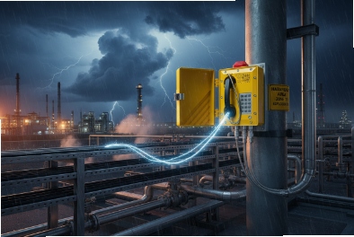
Lightning does not need a direct strike to break a phone. A nearby hit can push surge energy into PoE lines and ground paths, and the “emergency” phone goes offline without warning.
Lightning protection for explosion-proof telephones is a system design. It uses LPZ zoning, correct SPDs on power and Ethernet, short bonding paths, and a grounding plan that matches IEC 62305 and local codes.

A complete lightning protection blueprint for Ex telephones
Start with the real threat paths
A lightning event reaches an explosion-proof SIP telephone through four common paths:
1) Ethernet/PoE copper that runs outdoors or between buildings
2) AC power feeding a PoE switch, injector, or local PSU
3) Ground potential rise that forces current through bonding and shields
4) Induced surge from long parallel runs near lightning down conductors, pipe racks, or crane rails
A phone enclosure can be 316L and IP66, and it can still fail if surge energy enters through the RJ45 and finds a weak return path through the PCB.
Treat the phone like a network edge device, not a “simple handset”
Explosion-proof telephones are often SIP endpoints. So the weakest parts are:
-
the Ethernet PHY and magnetics
-
the PoE DC-DC converter
-
keypad and hook inputs that connect to long internal harnesses
-
audio amplifier paths that can latch or pop under fast transients
A good protection plan protects the phone and also protects the switch port. If only the phone is protected, the switch can still be damaged and take down multiple endpoints.
Use “defense in depth” instead of one big protector
A single SPD rarely solves everything. Lightning protection works best in layers:
-
Building entry SPD layer (where cables enter a cabinet or building)
-
Distribution SPD layer (inside the panel or network cabinet)
-
Point-of-use SPD layer (close to the phone or at the outdoor junction box)
Each layer reduces the surge energy that reaches the next layer. This also improves lifetime because each device sees less stress.
A practical architecture table that fits most petrochemical sites
| Location in the system | Main risk | Protection element | What it protects |
|---|---|---|---|
| Service entrance / main panel | Direct lightning current and switching surges | Type 1 or combined Type 1+2 SPD | Switches, injectors, whole cabinet |
| Network cabinet / distribution | Residual surge + EFT noise | Type 2 SPD + good bonding | PoE switch power rails |
| Copper line entry point | Induced surge on long runs | Ethernet/PoE surge protector 1 (signal SPD) | Switch port and phone port |
| Outdoor equipment point | Local coupling and GPR | Point-of-use SPD + bonding check | Endpoint stability and uptime |
This blueprint works for tank farms, loading racks, and offshore modules. The details change by standard and by installation style, so the next sections break it down in a way that you can copy into a project spec.
If the protection plan is clear on paper, commissioning becomes faster. If it is vague, the site adds random protectors and creates ground loops that cause new failures.
Now the first step is always standards, because standards decide where SPDs sit, what waveforms apply, and how bonding is validated.
Which standards guide design and installation—IEC 62305, IEC 61643-11/21, IEEE Std 142, and NFPA 780 for petrochemical sites?
Lightning protection fails when the team mixes rules from different worlds and never agrees on a single method.
IEC 62305 guides the overall lightning protection system and the LPZ zoning method. IEC 61643-11 covers SPDs for low-voltage power systems, and IEC 61643-21 covers SPDs for telecom and signal lines like Ethernet. IEEE Std 142 supports grounding and bonding practice, and NFPA 780 is a common installation reference in North America.
IEC 62305 sets the logic: risk, zones, and bonding
IEC 62305 2 is often used as the “system brain.” It helps the project team:
-
decide if an LPS is needed and what level
-
define Lightning Protection Zones (LPZ 0, LPZ 1, and deeper zones)
-
define bonding at zone boundaries
-
define separation distance and routing rules
For explosion-proof telephones, LPZ thinking is very practical. A phone on a loading rack is often in an exposed zone. A switch cabinet is often in a more protected zone. The boundary between them is where surge devices belong.
IEC 61643 splits power SPDs and signal SPDs
IEC 61643-11 is about low-voltage power SPDs. This is where Type 1, Type 2, and Type 3 live. IEC 61643-21 is about SPDs for signal and telecom lines. This is where Ethernet protectors and signal arresters live.
That split matters because many projects protect only AC power and forget the data line. In real failures, the Ethernet line is often the damage path.
IEEE Std 142 and NFPA 780 help with grounding and installation discipline
A lightning plan is only as strong as the grounding and bonding work. IEEE 142 helps teams speak the same grounding language. NFPA 780 3 is a common reference for air terminals, down conductors, bonding to metal bodies, and installation practice.
In petrochemical sites, local codes and owner standards can override small details. Still, these references keep the design consistent. They also help during audits and insurance reviews.
How to write a clean standard clause for tenders
A useful clause is short and direct:
-
“Lightning protection and surge coordination shall follow IEC 62305 LPZ principles.”
-
“Power SPDs shall comply with IEC 61643-11, and signal/Ethernet SPDs shall comply with IEC 61643-21.”
-
“Grounding and bonding shall follow the site grounding standard and recognized practice (IEEE 142 / NFPA 780 where applicable).”
A standards-to-deliverables table for procurement
| Standard reference | What it controls | Deliverable you should request | Why it helps |
|---|---|---|---|
| IEC 62305 | LPZ zoning, bonding, routing logic | LPZ drawing + SPD placement plan | Stops random SPD placement |
| IEC 61643-11 | Power SPD types and ratings | SPD datasheets with test class and waveform | Makes kA numbers meaningful |
| IEC 61643-21 | Signal line SPD performance | Ethernet SPD specs: PoE support and bandwidth | Protects switch ports and phones |
| IEEE 142 / NFPA 780 | Grounding and installation discipline | Grounding layout + bonding details | Reduces loop and impedance issues |
Once the standards are agreed, the next decision is surge protection selection. This is where many projects waste money or under-protect the real path.
Which surge protection should be selected—Type 1/2/3 SPDs, PoE/Ethernet arresters, and 10/350 μs kA ratings?
A “big kA SPD” sounds safe, but it can be the wrong device in the wrong place. Then the phone still dies through the Ethernet port.
Type 1 SPDs are used at service entrances and can be rated for 10/350 μs impulses. Type 2 SPDs are used at distribution panels and are often based on 8/20 μs ratings. Type 3 SPDs are used close to sensitive equipment. For SIP/PoE phones, Ethernet/PoE arresters are critical on outdoor copper runs and should match PoE power level, bandwidth, and grounding method.

Understand what the waveform rating is telling you
Lightning surge ratings are tied to waveforms:
-
10/350 μs is commonly used for high-energy lightning current at the entrance level (Type 1 intent).
-
8/20 μs is commonly used for lower-energy surges in distribution (Type 2 intent).
-
Point-of-use devices focus on limiting voltage close to equipment, and they rely on upstream devices to take the bigger energy.
This matters because a Type 3 device cannot replace a Type 1 at the service entry. It will fail early because it sees too much energy.
Select power SPDs by location and by coordination
For a network cabinet that powers many phones:
-
Put a Type 1 or Type 1+2 SPD at the building service entrance or main distribution board.
-
Put a Type 2 SPD at the cabinet feed or distribution panel.
-
If the phone system has a local AC adaptor or injector near the endpoint, add a Type 3 close to that sensitive equipment.
Coordination is as important as the SPD rating. The leads must be short and bonded correctly, or the clamping voltage rises and the phone still gets hit.
Ethernet/PoE arresters are not optional for outdoor copper
For explosion-proof SIP telephones, the Ethernet line is often the highest-risk path. A good Ethernet/PoE arrester should be selected with these criteria:
-
Supports the PoE standard 4 in use (often 802.3af/at and sometimes 802.3bt in high-power designs)
-
Supports the needed data rate (100M or 1G)
-
Has low insertion loss and does not break VLAN/QoS behavior
-
Has a clear bonding method for shield and protector earth
-
Has a specification that states surge waveform capability and clamping behavior
A selection table that fits most industrial phone networks
| Protection point | Device type | Key rating to check | Practical note |
|---|---|---|---|
| Main service entrance | Type 1 or Type 1+2 SPD | 10/350 capability and Iimp | Protects the whole site feed |
| Sub-panel / cabinet feed | Type 2 SPD | In/Imax 8/20 ratings and Up | Protects cabinet power rails |
| Near sensitive AC device | Type 3 SPD | Low Up and coordination | Protects injectors and PSU outputs |
| Copper Ethernet to outdoor phone | Ethernet/PoE SPD | PoE support + bandwidth + grounding | Often the main failure path |
A common mistake in petrochemical projects
Some teams install only cabinet power SPDs and assume PoE makes the edge safe. In reality, the long outdoor copper run can carry induced surges even if the cabinet power is clean. The Ethernet SPD at the right zone boundary is often the best value device in the whole plan.
Now SPDs only work as well as the grounding and bonding around them. The next section focuses on enclosure bonding and earth quality, because this is where “good hardware” becomes “bad performance” in the field.
How should enclosures be grounded and bonded—equipotential bars, ≤10 Ω earth, short leads, exothermic welding, and test points?
A lightning surge is a high-frequency event. So impedance and lead length matter as much as earth resistance.
Explosion-proof telephones should be bonded into the site equipotential bonding network using a dedicated earth stud and short, wide bonding conductors. Many owners target ≤10 Ω earth resistance as a practical benchmark, but low impedance bonding is the real goal for surge control. Exothermic welding is often used for durable bonds in outdoor petrochemical sites, and test points help verify continuity during commissioning and maintenance.

Equipotential bonding is the first rule
For lightning protection, the goal is simple: metal parts should rise and fall together during an event. If the phone housing is bonded and the nearby steel is bonded, the voltage difference is smaller. So the current is less likely to jump through the electronics.
A practical bonding plan includes:
-
a site equipotential bonding 5 bar in the cabinet or local area
-
a dedicated bonding conductor from the phone earth stud to local bonded steel or a bonding bar
-
bonding of cable shields and SPDs at a defined point
Keep leads short and wide
Long thin wires add inductance. Inductance raises the transient voltage during a surge. In the field, “short and wide” is the easy rule:
-
keep the SPD earth lead as short as possible
-
use wider straps where the owner standard allows
-
avoid loops and sharp bends
-
bond at the boundary, not at random points along the cable
How 316L enclosures should be treated
316L stainless 6 does not guarantee electrical continuity at hinges, covers, and glands. A lightning plan should include:
-
a clear external earth stud on the enclosure
-
conductive paths across hinges or covers when the design includes moving parts
-
glands that maintain a reliable bond where shield termination is required
This is also important for ESD performance and for long-term corrosion stability.
Earth resistance targets should not hide the impedance reality
Many documents request ≤10 Ω. Some owners demand lower. The number helps as a basic quality check, but lightning is fast. So the bonding layout often matters more than the resistance number.
A good approach is:
-
meet the site earth resistance target
-
also verify continuity and bonding quality with practical tests and visual checks
Test points and traceability save time later
A test point near the phone or at the local junction box makes maintenance easier. It lets a technician verify:
-
bonding conductor continuity
-
shield bond status
-
SPD earth connection integrity
A grounding and bonding checklist table
| Item | What to do | What it prevents |
|---|---|---|
| Phone earth stud | Bond to local equipotential point | Floating enclosure and high touch voltage |
| SPD earth lead | Keep short, wide, direct | High clamping voltage due to inductance |
| Shield bonding | Follow one consistent rule | Noise loops and surprise surge paths |
| Joints and hinges | Add bonding strap if needed | Intermittent continuity in stainless assemblies |
| Test points | Provide access for checks | “No fault found” maintenance cycles |
Once bonding is correct, the final part is wiring protection. This is where LPZ zoning becomes a real installation plan with cable routes, junction boxes, and fiber choices.
How should field wiring be protected—LPZ zoning, shielded cables, fiber uplinks, isolated power supplies, and outdoor junction boxes?
Outdoor copper is the easiest way for lightning energy to reach an endpoint. Wiring protection is the part that keeps the phone online after storms.
Field wiring should follow LPZ zoning: protect at zone boundaries, reduce outdoor copper exposure, use shielded cable with a clear bonding plan, and use fiber uplinks where possible. Outdoor junction boxes can host Ethernet/PoE SPDs in a safer zone. Isolated power supplies and proper cabinet SPDs help keep surge energy out of the core network.

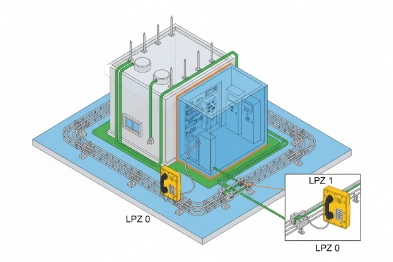
Apply LPZ logic to a phone network
A simple LPZ view works well:
-
The phone on a rack or perimeter wall is near LPZ 0/LPZ 1 boundary.
-
The outdoor cable route is a coupling zone.
-
The cabinet interior is a deeper zone.
The best SPD locations are usually:
-
where the cable enters a building, cabinet, or bonded junction box
-
where the cable transitions from outdoor to indoor routing
-
before sensitive switch ports when long runs are unavoidable
Use fiber when the run is long and exposed
Fiber breaks the conductive path. That is why it is one of the best lightning controls. In many projects, this design is simple:
-
use fiber from control room or core switch to an outdoor cabinet
-
keep the last copper segment short inside the protected cabinet
-
power the local PoE switch with well-bonded power SPDs
Fiber costs more up front, but it often reduces long-term failures and service calls.
Shielded cable helps only when bonding is consistent
Shielded Ethernet can reduce radiated coupling and can offer a cleaner return path for surge energy. Still, shielded cable creates new decisions:
-
bond shield at one end or both ends
-
how to bond through glands and junction boxes
-
how to keep the bond stable in corrosive environments
In harsh industrial sites, the simplest approach is “one documented rule that the whole project follows.” Random shield bonds create ground loops and can make audio noise worse.
Outdoor junction boxes are useful boundary devices
A good outdoor junction box 7 can:
-
host an Ethernet/PoE SPD
-
provide a local equipotential bond point
-
keep surge devices out of the hazardous area when the phone is in Zone 1/2 and the junction box is placed in a safer zone
-
provide a service point so technicians can replace SPDs without opening the Ex telephone
For hazardous sites, this is a big maintenance advantage. It reduces the need to open Ex enclosures and it keeps the surge device replacement simple.
Isolated power supplies and cabinet SPD coordination
If a PoE switch is powered from AC, the cabinet needs correct Type 1/2 SPDs upstream. If a DC system is used, the DC feed also needs surge control. Isolation helps reduce how much surge energy travels into the core network, but it does not replace proper bonding and SPDs.
A field wiring design table for petrochemical phones
| Design choice | Best practice | Why it works |
|---|---|---|
| LPZ boundary protection | Install SPDs at cable entry 8 points | Stops surge energy before it spreads |
| Fiber uplink | Use fiber for long exposed routes | Breaks the conductive surge path |
| Copper segment | Keep short and inside protected zones | Reduces coupling length |
| Outdoor junction box | Place SPDs and test points there | Easier service and safer maintenance |
| Shielded Ethernet | Use only with a clear bonding plan | Avoids noise loops and unstable grounding |
| Routing | Avoid long parallel runs with down conductors | Reduces induced surge |
In my own site discussions, the simplest success pattern is clear: fiber where possible, Ethernet SPDs at boundaries, and bonding that is short and verifiable. This pattern is easy to document and easy to maintain. It also keeps uptime high after storms, which is what the phone is there for.
Conclusion
Lightning protection for Ex telephones needs LPZ planning, coordinated SPDs on power and Ethernet, short bonding paths, and disciplined wiring that reduces exposed copper and keeps grounding verifiable.
Footnotes
-
[Devices that protect electrical equipment from voltage spikes by diverting excess current.] ↩
-
[International standard for lightning protection system design, including risk assessment and zoning.] ↩
-
[Standard for the installation of lightning protection systems, ensuring safety and compliance.] ↩
-
[IEEE standards defining Power over Ethernet technology for delivering power and data.] ↩
-
[Technique of connecting metalwork to the same earth potential to prevent dangerous voltages.] ↩
-
[Corrosion-resistant stainless steel commonly used for durable outdoor enclosures.] ↩
-
[Enclosures used to protect electrical connections and facilitate wiring distribution.] ↩
-
[Critical points where cables enter enclosures, requiring proper sealing and protection.] ↩


