
A SIP Ex phone can call perfectly, but a site still needs real I/O for strobes, sirens, and gate workflows. Without dry contacts, the “emergency” system stays manual.
Most explosion-proof telephones provide 1–2 dry-contact inputs and 1–2 relay outputs as a standard configuration. Higher I/O counts are possible through optional expansion boards or external I/O modules, but 2 in/2 out is the most practical “sweet spot” for industrial projects.

A practical way to specify dry-contact I/O for Ex telephones
Dry contacts solve three common industrial needs
Dry-contact ports are used for:
-
Alarm triggering: emergency button starts beacon, siren, or horn.
-
Status reporting: SCADA or PLC reads off-hook, emergency, or fault state.
-
Access control: trigger door strike, gate opener, or call permission signals.
In hazardous sites, dry contacts are often the fastest and most trusted integration method because they do not depend on API stability or PBX features.
“How many ports” depends on the workflow, not the phone model
A phone at a loading rack usually needs:
-
1 input for a tamper or door contact
-
1 input for an external alarm or local trigger
-
1 relay output for strobe/siren
-
1 relay output for door strike or PAGA trigger
That is why 2 in/2 out covers many real installations.
Keep the wiring safe and maintainable
In Zone 1/2 1 areas, opening an Ex d enclosure can be controlled and slow. The more wiring that enters the phone, the more glands, seals, and maintenance steps the site owns. A good I/O plan balances integration needs with service simplicity.
| I/O need | Typical channels required | Better design choice |
|---|---|---|
| Basic emergency alert only | 1 out | 1 relay output is enough |
| Alert + door strike | 2 out | 2 relay outputs avoids extra modules |
| Tamper + external trigger + alert | 2 in + 1 out | 2 in/1 out works well |
| Full workflow at gates | 2 in + 2 out | Most common for video/guard workflows |
| Many signals to SCADA | More than 4 total | Use external I/O module 2 + PLC mapping |
A strong tender spec does not only ask “how many ports.” It asks for input type, relay rating, wiring method, and Ex-safe installation details. The next sections give clear targets that match how integrators build systems in refineries and terminals.
If the project uses PAGA or access control, dry contacts are usually the simplest bridge between SIP and OT.
Now let’s answer the standard channel counts first.
How many dry-contact I/O channels are standard—1 in/1 out, 2 in/2 out, or more?
Different vendors ship different defaults, but the pattern in industrial SIP endpoints is consistent.
Standard dry-contact configurations are usually 1 in/1 out or 2 in/2 out. 1 in/1 out fits simple emergency alert needs. 2 in/2 out fits most gate, rack, and plant-floor workflows. More channels are typically delivered through optional boards, external I/O expanders, or a small PLC in a junction box.

When 1 in/1 out is enough
1 input and 1 relay output works well when:
-
the phone needs one external trigger (like a panic input)
-
the phone needs one local output (like a beacon)
It is also a good fit when the plant already has a PLC nearby and the phone I/O is only a backup.
Why 2 in/2 out is the most useful baseline
2 inputs and 2 outputs cover common workflows:
-
Input 1: tamper or cover switch
-
Input 2: external alarm trigger or door contact
-
Output 1: strobe/siren
-
Output 2: door strike, gate release, or PAGA trigger
It also gives room for future changes without replacing hardware.
When “more I/O” is better done outside the phone
If the site wants:
-
multiple alarm zones,
-
multiple interlocks,
-
or full SCADA tag sets,
then it is cleaner to add a dedicated I/O module or PLC 3 in a protected cabinet. This keeps the phone enclosure simpler and reduces gland count.
| Channel count | Best fit | Why it works | What to watch |
|---|---|---|---|
| 1 in / 1 out | Simple emergency call point | Low wiring and simple service | Limited future expansion |
| 2 in / 2 out | Gates, racks, plant floor | Covers typical workflows | Confirm relay rating matches load |
| >2 in/out | Complex automation | Better via external I/O | More wiring and integration work |
Next, channel count is only useful when the electrical rating is correct. A relay that can’t drive the strobe load is a design failure.
What contact ratings are supported—NO/NC, 12–30VDC, 1–3A, and opto-isolated inputs?
A relay output is not a power supply. Many failures come from driving inductive loads directly without a proper interface.
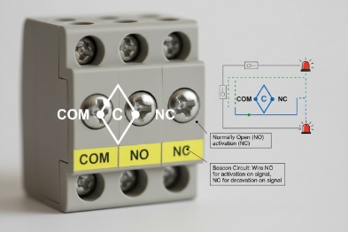
Most Ex telephone relay outputs are dry contacts with NO/NC (often with COM) and are designed for low-voltage control, commonly in the 12–30 VDC range. Typical current ratings fall around 1–3 A depending on design. Inputs are often dry-contact sense inputs and many industrial designs use opto-isolated inputs to reduce noise and protect the CPU. Exact ratings must be confirmed on the model datasheet and terminal block marking.
Relay outputs: what to verify
For each relay output, confirm:
-
contact form: NO/NC/COM or NO/COM only
-
maximum voltage and current (DC and AC if listed)
-
whether the rating is for resistive load only
-
whether the relay can handle inductive loads or requires a snubber 4 /diode
In industrial use, many outputs are used as control signals to:
-
a strobe controller,
-
a door access controller,
-
a paging controller input,
-
or a PLC input.
That is safer than driving a horn directly.
Inputs: dry contact vs powered input
Inputs typically fall into two types:
-
dry contact input: the phone senses an open/close contact
-
powered input: the phone expects a voltage level (less common in Ex phones)
Opto-isolated inputs 5 are useful because they:
-
reduce noise issues on long field wires
-
reduce damage risk during ESD and surge events
-
improve stability in high EMI areas
A practical rating table for tenders
| I/O type | Best practice spec language | Why it matters |
|---|---|---|
| Relay output | “Dry contact, NO/NC/COM, rated ≥30 VDC, ≥1 A (resistive)” | Matches common control circuits |
| Inductive load note | “Inductive loads must be driven via interposing relay” | Prevents relay welding and resets |
| Input type | “Dry-contact input, opto-isolated preferred” | Improves stability |
| Cable length | “Field wiring length and shield rules defined” | Long wires create noise problems |
If the project drives strobes or PAGA horns, it is smarter to trigger a controller input rather than driving the load through the phone relay.
Now we can connect this to real workflows: SIP DTMF triggers, schedules, and API calls.
Can relays trigger strobes, door strikes, or PAGA horns via SIP DTMF, schedules, or API?
A phone relay is most valuable when it can be controlled reliably from the voice workflow. That means the phone must support defined trigger logic.
Yes. Relays can be triggered by events such as emergency button press, call state changes, DTMF commands during a call, schedules, or HTTP/API commands, depending on the phone firmware. In industrial projects, the most reliable method is event-based triggers (emergency input or call connected) and DTMF triggers controlled by a PBX or dispatch system, with outputs driving strobe controllers, door controllers, or PAGA paging inputs.
Three common trigger models that work on site
1) Local event triggers (most reliable)
-
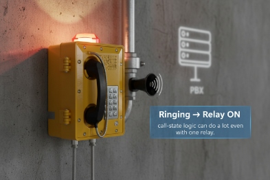
Emergency button → Relay ON → Strobe/Siren
-
Input contact closes → Relay ON → Paging controller trigger
This works even if the network is congested because the trigger is local.
2) DTMF triggers (dispatch-friendly)
A dispatcher calls the phone or a group, then sends DTMF 6 to:
-
activate strobe for attention
-
unlock a gate
-
trigger a horn zone input
This is common because it is easy to train operators.
3) API triggers (best for automation)
API triggers are useful for:
-
linking access control events to relay actions
-
tying alarms to ticketing systems
-
integrating with a site safety platform
Still, API triggers require strong security controls and stable firmware documentation.
Trigger-to-load wiring: use interposing relays for power loads
Many field devices draw more than a phone relay should handle, or they are inductive. A safer pattern is:
-
Phone relay output drives a control input or an interposing relay
-
That relay drives the high-current load
-
A suppression diode or snubber protects the circuit
A workflow table for refineries and terminals
| Use case | Trigger method | Relay output role | Recommended external device |
|---|---|---|---|
| Local beacon on emergency | Local emergency event | Turn beacon controller input ON | Beacon/strobe controller |
| Gate release | DTMF or API + permission | Pulse door strike controller input | Access control panel |
| PAGA horn zone trigger | Local input or DTMF | Start paging input | Paging controller 7 or SIP paging server |
| Alarm test schedule | Schedule trigger | Pulse relay for test | Local test circuit with logging |
The final piece is wiring for Ex safety. Dry contacts look simple, but in Zone 1/2 the wiring method, glands, and grounding decide whether the installation is compliant and stable.
How are Ex-safe connections wired—barriers, shielded cables, gland selection, and grounding for Zone 1/2?
Many failures happen after installation, not in the factory. A phone can lose IP rating and Ex integrity when the wrong gland is used or a shield is bonded randomly.
Ex-safe wiring depends on the protection concept and the zone. For Zone 1/2 Ex d phones, use certified cable glands and correct sealing practices, and keep bonding strong. If circuits are treated as intrinsically safe (Ex i) for field wiring, use the correct barriers or galvanic isolators and keep segregation rules. Shielded cables can help with noise, but shields must be bonded according to the site earthing plan to avoid ground loops.

Step 1: know whether the I/O circuit is Ex i or “simple apparatus”
Dry-contact I/O can be implemented in different ways:
-
As a basic internal circuit within an Ex d enclosure, with wiring protected by the enclosure and entry glands.
-
As an intrinsically safe loop (Ex i [^8]), where barriers or isolators limit energy for field wiring outside the Ex enclosure concept.
The project should not guess. The certificate, control drawing, or installation instructions define what is allowed.
Step 2: glands and cable entry decide the real IP and long-term reliability
For Zone 1/2:
-
Use certified Ex glands that match the cable type (armored or unarmored).
-
Use certified blanking plugs for unused entries.
-
Apply correct torque and sealing washers.
-
Provide strain relief so the cable does not pull the gland.
If the I/O wiring runs outdoors, choose UV-stable cable jackets and protect from abrasion.
Step 3: grounding and equipotential bonding
Bond the enclosure using:
-
an external earth stud
-
a short bonding conductor to the equipotential bar
-
continuity across covers and hinges if needed
For shielded cables:
-
define the shield bonding rule (one end or both ends) by site standard
-
keep it consistent across cabinets and junction boxes
-
avoid random bonding that creates noise loops
Step 4: barriers and segregation when Ex i is used
If the project uses Ex i for field wiring, then:
-
barriers/isolators sit in a safe area or certified enclosure
-
blue IS wiring is segregated from non-IS wiring
-
installation follows the control drawing [^9]
This approach is often chosen when long field wiring and human touch points need added safety.
A wiring checklist table for installers
| Item | What to do | What it prevents |
|---|---|---|
| Gland selection | Certified Ex gland matched to cable | Loss of Ex rating and leaks |
| Shield handling | Follow one bonding rule | Ground loops and false triggers |
| Barrier use | Use isolators if Ex i loop is required | Ignition risk on field wiring |
| Cable routing | Separate from high-power runs | Noise and nuisance alarms |
| Bonding | Short conductor to equipotential bar [^10] | Floating enclosure and ESD issues |
| Documentation | Record wiring and terminal IDs | Fast maintenance and audits |
If the project wants more than 2 in/2 out or wants SCADA mapping, it is often smarter to place a small I/O module in a nearby safe junction box and keep the phone wiring minimal. That reduces glands and makes service safer in Zone 1.
Conclusion
Most explosion-proof telephones provide 1–2 inputs and 1–2 relay outputs, with 2 in/2 out as a common industrial target. Confirm contact ratings, use safe trigger logic, and wire with certified glands, proper bonding, and barriers when Ex i loops are required.
Footnotes
-
[Hazardous area classification based on the frequency and duration of explosive gas atmospheres.] ↩
-
[Device that connects sensors and actuators to a network for monitoring and control.] ↩
-
[Programmable Logic Controller used for automation of industrial electromechanical processes.] ↩
-
[Circuit used to suppress voltage spikes and protect switching components like relays.] ↩
-
[Components that transfer electrical signals between two isolated circuits using light.] ↩
-
[Signaling method using dual-tone frequencies for telecommunication control.] ↩
-
[System ↩


