
A fire event is not the time to discover that the phone cannot trigger strobes or call the control room. The gap shows up fast and it hurts response time.
Yes. Explosion-proof telephones can integrate with fire alarm systems using relays, supervised inputs, or IP gateways, but the interface must follow NFPA 72 or EN 54 rules and keep hazardous-area wiring safe and isolated.

Fire alarm integration for hazardous-area telephones
Two systems, two jobs, one workflow
A fire alarm system is life safety. It must behave in a predictable way. A SIP telephone system is communications. It must stay available and give operators fast control. Integration works best when each system keeps its main job, and the “bridge” is limited, documented, and testable.
In most refinery and terminal projects, the fire panel stays in a safe area. The Ex telephone sits in Zone 1/2 areas. The bridge usually sits at a boundary, like a cabinet or junction box, where maintenance is easier. This reduces risk and reduces the number of cables entering the Ex enclosure.
What “integration” usually means in the field
Integration is typically one or more of these:
-
Fire panel triggers a phone output: strobe, siren enable, or paging trigger
-
Phone triggers a fire input: an alarm call point or “emergency phone active” status
-
SCADA and security logs align with fire events: time stamps and event codes
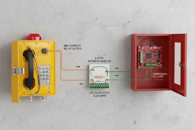
The cleanest method is dry contact to dry contact through a listed interface module. It is simple. It is also easy to prove during commissioning.
Fire alarm circuits are not like normal control circuits. Many are supervised 1. Many require listed equipment. In practice, the Authority Having Jurisdiction (AHJ) or project fire engineer decides what is allowed. A project can still use an Ex telephone to start a workflow, but the connection method must not bypass supervision or create an unsafe load on the panel.
Integration options at a glance
| Integration goal | Recommended method | Fire system impact | Voice system impact |
|---|---|---|---|
| Trigger strobe/horn near a phone | Phone relay to listed interface or local controller | Minimal | Simple configuration |
| Send “phone emergency active” to FACP | Phone relay into supervised input module | Supervised and auditable | Very stable |
| Auto-call control room on fire alarm | FACP relay to SIP trigger input or gateway | Minimal | Needs call routing rules |
| Site-wide announcements | Fire panel triggers paging controller / PAGA 2 | Controlled by fire logic | Needs priority paging design |
A good plan keeps the bridge small and reliable. The next sections explain the interface choices, the codes, the operating workflow, and the installation rules that keep both systems compliant.
If the project has one rule, it should be this: never connect a fire alarm NAC 3 directly to a phone. Use the correct interface and keep the supervision intact.
Now let’s start with the interface methods, because that decision shapes everything else.
A clean interface choice also reduces the number of “custom” features a vendor must promise.
Which interfaces link to a fire panel—dry-contact relays, supervised inputs with EOL resistors, 24V NAC, or IP gateways to addressable FACP?
A wrong interface can create nuisance troubles on the panel or silence a notification circuit. That is a serious failure mode.
The most common links are dry-contact relays into supervised FACP inputs (with EOL resistors) and listed interface modules. NAC circuits should be driven by fire-listed devices, not by a phone relay. Addressable integration usually needs a listed IP or protocol gateway approved by the fire system vendor.
Dry contacts: the safest “bridge language”
Dry contacts are popular because they do not carry power. The phone can provide a relay output. The fire panel can read an input. That relay can represent:
-
Emergency call initiated
-
Phone fault
-
Door release request (through a fire-controlled interlock)
-
Paging trigger request
Dry contacts work well when the fire panel input is supervised through an interface module. The module handles EOL 4 supervision and makes the panel happy.
Supervised inputs with EOL: keep the panel honest
Supervised inputs detect open and short conditions. That is important for life safety. When the phone provides a relay, the common method is:
-
Phone relay closes a circuit
-
A listed module or supervised input reads the change
-
EOL resistor stays at the correct location as required by the panel design
This keeps the circuit auditable and reduces false “normal” states caused by broken wires.
24V NAC: treat it like fire alarm power, not a control line
Notification Appliance Circuits (NAC) are designed to power horns, strobes, and sounders that are listed for fire alarm service. A phone relay should not be used as a NAC load or a NAC switching device unless the interface is listed and designed for that purpose. A safer pattern is:
-
Fire panel NAC powers listed strobes/horns
-
Phone triggers a separate industrial beacon only if the fire engineer allows it
-
Or the phone relay triggers a listed module that is designed for alarm circuits
Addressable and IP gateways: only when the fire vendor supports it
Some sites want addressable points for “Emergency Phone Activated.” That is possible, but it is normally done through:
-
the fire vendor’s listed addressable input module
-
or a listed gateway that the vendor supports
A generic IP gateway is not automatically accepted by an AHJ. The acceptance depends on listing and system compatibility.
| Interface type | Best use | Common mistake | Better requirement line |
|---|---|---|---|
| Phone relay → supervised input | Send phone state to FACP | No supervision, wrong resistor placement | “Use listed module, supervised input with EOL” |
| FACP relay → phone input | Trigger auto-dial or paging | Driving phone directly from NAC | “Dry contact trigger only, no NAC load” |
| NAC → devices | Horn/strobe circuits | Using phone relay to switch NAC | “NAC loads must be listed fire devices” |
| IP gateway | Rich data | Unlisted integration in fire loop | “Gateway must be accepted by fire vendor/AHJ” |
Once the interface is chosen, the next step is compliance. Fire systems are regulated by codes and listings, and hazardous areas add another layer.
What codes must be met—NFPA 72, UL 864 or EN 54, plus ATEX/IECEx zoning for emergency audio and alarm priority?
A project can pass the factory test and still fail the site inspection. Most failures come from assuming “industrial rules” apply to fire systems.
Fire alarm interfaces must follow local fire codes and listing rules like NFPA 72 with UL-listed fire alarm control equipment in many regions, or EN 54 systems in others. Hazardous-area devices still need ATEX/IECEx zoning compliance, and alarm priority must not be weakened by voice traffic or network congestion.

Fire code sets the life-safety rules
NFPA 72 5 governs how signals, supervision, and emergency communications should behave in many projects. In EU-style projects, EN 54 and local regulations govern similar topics. The key idea is consistent: the fire alarm system must keep control of life-safety signaling, and connected equipment must not reduce reliability.
When an Ex telephone is tied in, the fire engineer often asks:
-
Does this link add a failure point?
-
Is the circuit supervised?
-
Is the device or interface listed for the fire system?
-
Can it be tested and documented?
UL 864 and EN 54: understand the boundary
UL 864 6 applies to fire alarm control units and related equipment in many North America projects. EN 54 applies to fire detection and alarm system components in many EU projects. An Ex telephone is usually not a fire panel component. So the integration often relies on:
-
listed modules inside the fire system
-
or interface relays that are accepted by the AHJ and fire vendor
This is why a “general industrial relay” is not always accepted inside the fire system loop. The project should plan for the correct listed interface.
ATEX/IECEx zoning still applies at the field end
If the phone is in Zone 1/2 or in a classified dust area, it must meet the correct hazardous-area certification. The fire panel and its modules are typically in a safe area. This creates a boundary that must be managed:
-
cable routing
-
glands
-
barriers or isolators when needed
-
segregation between fire circuits and hazardous-area circuits
The safest design keeps fire system equipment in safe areas and limits what crosses into the hazardous zone.
Alarm priority: voice systems must not delay life safety
If the phone system participates in paging or alerting, priority is critical. A fire event must override routine paging. It must also remain audible in noisy environments. That means:
-
paging priority rules
-
bandwidth/QoS rules
-
and a fallback path if the SIP server is down
| Compliance item | What it controls | What to ask during design review |
|---|---|---|
| NFPA 72 / local code | Supervision, annunciation, testing | “Show circuit class, supervision, and test plan” |
| UL 864 / EN 54 | Listing of fire components | “Which modules are listed and where are they used?” |
| ATEX/IECEx | Hazardous area safety | “Zone/Gas group/Ta matches installation point” |
| Alarm priority | Emergency overrides | “Paging and alarms preempt normal calls” |
Once compliance rules are clear, the workflow becomes the next decision. Integration should not be “just a wire.” It should be an operating process that crews understand in a noisy refinery.
How should alarm workflows operate—auto-dial triggers, priority paging, siren/strobe activation, and fireman’s telephone loops across noisy refinery and terminal areas?
If the workflow is unclear, operators will improvise. Improvisation is slow and it fails under stress.
A strong workflow uses simple triggers and clear priorities: fire panel outputs can trigger auto-dial and emergency paging, while Ex telephone relays can activate local strobes and report “emergency active” back to the panel. In very noisy areas, directional horns and PAGA coverage matter more than one handset sounder.

Auto-dial triggers: simple and effective
A common workflow is:
-
Fire panel goes into alarm
-
A panel relay closes
-
The telephone system receives the trigger
-
The system auto-dials a control room group, dispatch, or security
This is useful because it creates a human response loop. A panel sounder gets attention. A phone call gets coordination.
To keep it reliable, the call target should be:
-
a group, not one person
-
with escalation and no-answer rules
-
with logs and time stamps
Priority paging and PAGA: the right tool for wide-area alerts
Refineries and terminals are loud. PAGA horns and speakers are designed for that environment. A phone can still help by:
-
triggering a paging controller input via relay
-
sending a multicast paging message
-
providing a “push-to-talk” paging call for incident commanders
The key is priority. Emergency paging must preempt routine announcements and remain stable during network load.
Local siren and strobe: use it as a local attention marker
Local strobes near the phone are useful for:
-
drawing responders to the call point
-
guiding a fire team through complex pipe racks
-
marking an “emergency station” location
A good design uses the phone relay to drive:
-
a strobe controller input
-
or an interposing relay that drives the beacon power
It avoids powering large loads directly from the phone relay unless the rating is clearly sufficient.
Fireman’s telephone concept: use the idea, not the exact legacy loop
In many industrial sites, the equivalent need is “a reliable emergency talk path for responders.” Some sites use dedicated emergency phones 7, dispatch consoles, or intercom loops. The idea is:
-
responders have a known way to communicate
-
it works during high noise and high stress
-
it remains available when normal comms are overloaded
A SIP-based emergency phone system can support that goal when it has:
-
redundant power
-
redundant switching
-
and a known paging/dispatch process
| Workflow block | Trigger source | Primary action | Fallback action |
|---|---|---|---|
| Fire alarm to communications | FACP alarm relay | Auto-dial control room | Local PAGA trigger via relay |
| Phone to fire system status | Phone emergency relay | FACP supervised input alarm | SCADA alarm via PLC |
| Local guidance | Phone relay output | Strobe near call point | Beacon via independent controller |
| Wide-area alert | Paging controller | Priority paging/PAGA | Pre-recorded message from local controller |
Once the workflow is clear, installation becomes the final gate. Fire systems and hazardous areas both punish sloppy wiring. The next section focuses on survivability, redundancy, and safe isolation.
What installation rules ensure safety—fail-safe door release, 2-hour fire-rated cabling, UPS/PoE redundancy, and galvanic isolation between hazardous and fire-protected zones?
A good design can still fail because of one wrong gland or one shared power supply. That failure shows up during a real event.
Safe installation uses fail-safe door release logic controlled by the fire system, survivable cabling where required, redundant power for PoE and network switches, and galvanic isolation or barriers between hazardous-area field wiring and fire-protected control circuits.

Fail-safe door release: fire system stays in charge
Door release in a fire event is a life-safety function. The clean approach is:
-
Fire panel controls door release logic
-
The phone may request release (DTMF or API), but it should not override fire logic
-
The access controller should drop power or unlock per site fire strategy
This keeps compliance simple and avoids conflicts between security rules and life safety rules.
Fire-rated cabling and survivability: apply it where the code demands
Some circuits require survivability for a defined duration, often 2 hours 8 in certain emergency communication paths and critical installations. Industrial sites vary by jurisdiction and design basis. The safe approach is:
-
follow the project fire engineer’s survivability plan
-
route critical cables away from high fire risk areas
-
use rated cable, conduit, or pathway protection where required
The goal is not “fireproof everything.” The goal is to keep the emergency path alive long enough for response.
UPS and PoE redundancy: keep the phones alive during power events
SIP phones rely on network power and switching. A practical redundancy plan includes:
-
UPS for core switches and PoE switches feeding emergency phones
-
redundant power feeds where possible
-
monitoring of PoE power status
-
controlled reboot behavior and fast re-registration
For critical phones, it helps to separate them onto a dedicated PoE switch or a dedicated UPS circuit.
Galvanic isolation and barriers: keep boundaries clean
When circuits cross from safe areas into hazardous areas, isolation matters. Good practice includes:
-
interface modules in a safe cabinet
-
isolators or barriers 9 when required by the protection concept
-
clear segregation of wiring types
-
shield handling rules that match the site earthing plan
This also improves EMC behavior. It reduces false alarms from induced noise and surges.
Glands and grounding: the detail that protects Ex integrity
For Zone 1/2 installation:
-
use certified glands matched to cable type
-
seal unused entries with certified plugs
-
bond the enclosure to the equipotential network 10 with a short conductor
-
keep cable shields consistent and documented
| Installation rule | Why it matters | Field check |
|---|---|---|
| Fail-safe door release | Life safety priority | Door releases on fire alarm as designed |
| Survivable cabling where required | Keeps emergency path alive | Cable type and routing match drawings |
| UPS/PoE redundancy | Prevents silent phone outage | UPS runtime verified and alarms tested |
| Isolation/barriers | Protects zone boundary | Correct modules installed and labeled |
| Certified glands and bonding | Keeps Ex and IP rating | Torque marks, continuity test, visual seal check |
A final practical habit helps: treat integration points like safety devices. Label them. Record their wiring. Test them on a schedule. It reduces the “works today, fails later” risk.
Conclusion
Explosion-proof telephones can integrate with fire alarms using listed interfaces, clear priority workflows, and safe zone-boundary wiring. The best designs keep fire supervision intact and keep phones powered and logged during incidents.
Footnotes
-
[Fire alarm circuits monitored for integrity to detect open or short faults immediately.] ↩
-
[Public Address and General Alarm systems used for emergency notifications in industrial plants.] ↩
-
[Notification Appliance Circuit, a supervised output circuit for powering horns, strobes, and speakers.] ↩
-
[End-of-Line resistor used in supervised circuits to ensure wiring integrity.] ↩
-
[National Fire Alarm and Signaling Code standardizing fire alarm system installation and performance.] ↩
-
[UL standard for control units and accessories for fire alarm systems.] ↩
-
[Telephones specifically designed for reliable communication during emergencies.] ↩
-
[Cables tested to maintain circuit integrity during fire exposure for a specified time.] ↩
-
[Intrinsic safety barriers limiting energy to hazardous areas to prevent ignition.] ↩
-
[System connecting all metallic components to earth to prevent potential differences and sparks.] ↩


