
A weatherproof telephone can have IP67 sealing and metal housing, but if the hook switch fails early, the whole system becomes unreliable and every emergency call turns into a risk.
Most weatherproof telephones quote a hook switch lifecycle between 100,000 and 1,000,000 operations, with high-end industrial and marine models aiming closer to 500,000–1,000,000 mechanical cycles under rated load.

When planning an outdoor or industrial communication system, it makes sense to treat the hook switch like any other critical component. The lifecycle rating is not just a marketing number. It depends on test standards, temperature and humidity conditions, mechanical abuse tests, and even whether you can replace the hook module in the field. Let’s walk through these points one by one.
Which endurance standards verify hook switch life—IEC 60068 or vendor test plans?
Many buyers see “1,000,000 operations” in a datasheet and feel safe, but the real question is simple: who verified this number and under which test method?
Hook switch endurance is often validated with IEC 60068-based mechanical and electrical cycling, plus vendor-specific test plans that define contact load, switching speed, and pass/fail criteria.
Mechanical vs electrical lifecycle
Every hook switch has two different lives. Mechanical life describes how many times the mechanism can move between on-hook and off-hook before something wears or breaks. Electrical life describes how many times it can safely make and break the live circuit under a defined voltage and current. For many industrial and weatherproof telephones, mechanical life sits in the 500,000–1,000,000 range, while electrical life 1 can be lower, maybe 100,000–300,000 operations at a given load. So the “headline” number must always be read together with the contact rating.
Role of IEC 60068
IEC 60068 is a family of environmental and endurance test standards. Manufacturers often base their hook switch endurance tests on parts of IEC 60068 2, such as repetitive mechanical operation, dry and damp heat, and vibration. A typical vendor plan may say that the hook switch is cycled a fixed number of times at a constant rate, with a defined contact load that represents a real PSTN or internal line. The test then checks for increased contact resistance, welding, bounce, or failure to change state. The reference to IEC 60068 gives a common language between vendors and buyers.
Vendor-specific test plans
Even when IEC is mentioned, most companies still write their own detailed test plans. These plans include the exact test fixture, actuation force, stroke, speed, and rest periods. Some simulate real user behavior, such as fast repeated call setups on hotline phones. Others test at elevated temperature to compress years of field usage into a shorter lab test. When I review a hook switch spec, I look at how clearly the vendor describes this plan. A strong spec links the lifecycle number to a defined voltage, current, and test profile.
| Aspect | What It Means | Typical Value / Note |
|---|---|---|
| Mechanical life | Movements with or without load | 500k–1,000k operations |
| Electrical life | Operations under rated line load | 100k–300k at defined V/I |
| Standard reference | Basis for test method | IEC 60068 plus internal procedures |
| Test description | Details of cycling and inspection | Often in vendor “type test” document |
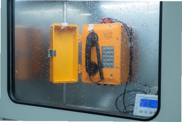
Under what temperature and humidity conditions were cycles validated?
A million cycles at room temperature in a dry lab sounds great, but most weatherproof telephones never live in that kind of friendly world.
Serious weatherproof telephone designs validate hook switch life across a temperature and humidity range, often from around -25 °C to +55/+70 °C and up to 93–95% RH, based on IEC 60068 profiles.
Why environment changes the real lifecycle
Hook switches sit just behind the front panel of the phone, close to the handset cradle. In hot climates the sun heats the housing, and internal temperature can rise far above ambient. In cold regions the switch sees repeated freeze–thaw cycles. High humidity and condensation can slowly oxidize contacts or change plastics. So a lifecycle measured only at +23 °C and 50% RH does not tell the whole story. For outdoor and industrial telephones, we care about how the switch behaves near the edges of its declared service temperature range 3.
Typical test envelopes for weatherproof units
Many industrial telecom products declare a working range such as -25 °C to +55 °C, sometimes up to +70 °C for short periods. Humidity tests often follow IEC 60068 damp heat 4 procedures, which hold the unit at high humidity, for example 93–95% RH, over many hours or days. A well-documented hook switch lifecycle will state if the cycling was done only at room temperature or at several points across this envelope. In more advanced test plans the switch may be cycled at low temperature, normal temperature, and high temperature to check for drift in actuation force and contact resistance.
Reading between the lines in the datasheet
When a datasheet states “1,000,000 mechanical operations” but stays silent on temperature and humidity, I assume the test happened under near-lab conditions. That can still be fine for indoor phones, but for coastal or chemical plants I prefer to see references like “tested at 85% RH” or “type tested after thermal cycling.” Some vendors run environmental stress before or after endurance cycling: for example, subject the entire telephone to temperature cycles from -25 °C to +70 °C, then verify the hook switch still meets its mechanical and electrical limits. This style of testing gives much more confidence that the switch will survive years of real outdoor use.
| Test Condition | Typical Values for Weatherproof Telephones |
|---|---|
| Operating temperature | -25 °C to +55 °C (sometimes up to +70 °C) |
| Storage temperature | -40 °C to +70 °C or higher |
| Relative humidity | Up to 93–95% RH (non-condensing or cyclic) |
| Lifecycle test point | Room temp only, or multiple points across range |
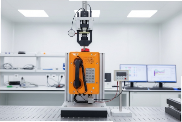
Does handset drop or side-impact testing affect hook durability?
In public or heavy industrial areas, people do not treat handsets gently. They drop them, slam them, and sometimes hit the cradle itself, which puts extra stress on the hook switch.
Handset drop and side-impact tests can stress the hook mechanism and its supports, so good designs combine high cycle ratings with mechanical tests that verify the hook still operates within spec after abuse.
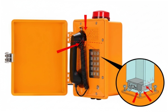
How handset abuse loads the hook
In many weatherproof telephones, the hook switch is either directly under the cradle or linked with a short lever or magnet. When a user drops the handset against the cradle or swings it on the armored cord, the impact force transfers into the cradle, housing, and hook structure. Over time, this can bend linkages, crack plastic supports, or shift the alignment of a reed switch 5 or microswitch. None of this shows up in a clean bench test where a robot actuates the switch gently a million times.
Typical drop and impact tests
To deal with this reality, serious vendors run drop tests with the real handset and cord. A common pattern is to drop the handset from a defined height, for example 1.2 m, onto the cradle or the housing surface, for dozens or hundreds of cycles. Side-impact tests may also strike the front or side of the unit with a pendulum or impact hammer (refer to IK impact testing 6) to simulate vandalism or accidental hits from tools. After these tests, the hook switch must still change state reliably, without sticking, double-activating, or failing to detect on-hook.
Combining endurance and abuse in one design
The best designs start by choosing a hook technology that handles both cycling and shocks well. Magnetic reed or Hall effect sensors 7 reduce exposed moving parts and often survive vibration and impact better than basic lever switches. The mechanical design around the hook routes impact into the sturdy housing or metal brackets, instead of into the delicate switch body. After the structure is set, the vendor validates the lifecycle with the abuse included: for example, run a defined number of drop impacts, then cycle the hook to its rated number, and only then measure the contact behavior.
From a project point of view, I treat cycle rating and impact tests as two sides of the same reliability story. A million operations in a quiet lab does not matter if one hard hit in the field knocks the hook out of alignment.
| Test Type | What It Simulates | Effect on Hook Switch |
|---|---|---|
| Handset drop | User dropping or slamming handset | Shock load on cradle and hook |
| Side impact | Tools, vandalism, accidental hits | Stress on housing and supports |
| Vibration | Machinery, traffic, wind | Long-term fatigue on moving parts |
| Post-test check | Functional operations and contact | Confirms durability after abuse |
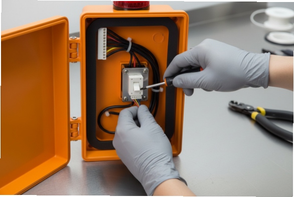
Are hook switch modules field-replaceable, with spare part numbers?
Even the best hook switch can fail after heavy use, so maintenance teams often ask one key question: can we replace the hook module in the field without scrapping the whole telephone?
Many industrial weatherproof telephones use modular hook switch assemblies that are field-replaceable, and serious vendors publish spare part numbers, wiring details, and replacement procedures.
Why field replacement matters for lifecycle planning
A high lifecycle rating reduces the risk of failure, but it does not make any component immortal. In critical systems like emergency phones, plant intercoms, or roadside call points, downtime is expensive and sometimes dangerous. If the hook switch fails, the line can stay off-hook, or the phone cannot seize the line when lifted. A field-replaceable module allows a technician to fix the problem quickly, without shipping the unit back to the factory or replacing the entire housing.
Types of hook switch modules
Manufacturers use several styles of hook design. Some are classic mechanical plunger or lever switches mounted on a small PCB. Others use a magnet and reed switch, or a proximity sensor 8 with no physical contact. In modular designs, this group of parts sits on a small subassembly with a connector or a clear terminal layout. The technician can remove the front panel or open the door, unplug or unscrew the old module, install the new one, and then test the on-hook and off-hook states with a simple multimeter or line tester.
Documentation and spare part systems
For a field-replaceable hook, documentation is just as important as mechanical design. Good vendors provide an exploded view drawing, a spare part code for the hook assembly, and step-by-step replacement instructions. Some even list recommended replacement intervals for very high-use sites, such as public transport stations or control rooms. When planning a rollout, I like to create a small spare parts kit 9: a few hook modules, handsets, and keypads, all with matching part numbers and clear labels. This helps local teams respond fast when any of these wear components shows signs of failure.
Linking lifecycle rating to maintenance strategy
The lifecycle rating is the starting point. A model rated at 1,000,000 mechanical operations under real load may run for many years even in busy locations. Still, having field-replaceable hook modules and spare part support gives a second safety net. It lets asset owners extend the total life of the telephone housing, cable entries, and mounting hardware, while only swapping the parts that actually wear out. This approach reduces both waste and downtime. (See sustainable maintenance practices 10)
| Feature | Advantage for End Users |
|---|---|
| Modular hook switch assembly | Fast replacement without full teardown |
| Published spare part numbers | Easier stocking and procurement |
| Clear replacement procedure | Short training for maintenance staff |
| High cycle rating + spares | Long service life with low downtime |
Conclusion
Hook switch lifecycle for weatherproof telephones depends on more than a single cycle number; it reflects test standards, environment, abuse testing, and whether you can swap the module in the field.
Footnotes
-
Explains mechanical vs. electrical life cycles in switches and factors affecting longevity. ↩
-
Overview of the IEC 60068 standard series for environmental testing of electrotechnical products. ↩
-
Discusses thermal management and operating temperature considerations for electronics. ↩
-
Details on humidity testing to evaluate product reliability in damp environments. ↩
-
Technical paper on reed switch characteristics, often used in durable hook mechanisms. ↩
-
Guide to IK impact ratings and testing procedures for enclosure robustness. ↩
-
Explanation of Hall effect sensors and their use in contactless switching applications. ↩
-
Overview of proximity sensors as reliable alternatives to mechanical switches. ↩
-
Best practices for managing spare parts inventory to minimize equipment downtime. ↩
-
Article on sustainable maintenance strategies to extend equipment life and reduce waste. ↩


