
Packet loss in a hazardous area is not just an IT issue. It can turn a clear emergency call into broken words when people feel pressure.
Explosion-proof telephones reduce VoIP packet loss by controlling congestion with QoS, using the right codec and jitter buffer, keeping PoE and cabling stable in EMI-heavy zones, and monitoring RTP with RTCP and switch counters to fix root causes fast.

What really causes packet loss in hazardous-area VoIP systems?
Packet loss is rarely “random.” In most industrial plants, loss comes from a small set of repeatable causes: queue congestion, microbursts, bad trust boundaries for QoS, duplex or speed mismatches, EMI-induced CRC errors, and unstable power. A hazardous-area telephone makes this harder because the cable runs are longer, the route passes motors and VFD panels, and maintenance windows are limited.
Congestion loss is the most common. A switch port can be clean at 10:00 and start dropping at 10:05 when a camera stream spikes or a PLC upload starts. Many plants also have traffic bursts, not smooth traffic. RTP 1 hates bursts. RTP wants small packets at steady timing. A single congested uplink can drop voice packets even when total bandwidth looks “fine” on paper.
Jitter becomes loss when the jitter buffer cannot absorb the variation. Some teams think “packet loss is only missing packets.” In voice systems, late packets are also lost. A jitter buffer that is too small turns jitter into loss. A jitter buffer that is too big adds delay and hurts talk flow.
Physical layer issues also look like packet loss. Bad shielding, poor bonding, water in a connector, or a PoE budget problem can cause retries, CRC errors, and link renegotiations. The voice stack sees missing RTP packets, but the root cause is not IP routing. It is a dirty link.
A short field example explains the pattern. One refinery had “VoIP loss on the Ex phones.” The SIP 2 server was blamed. The real issue was a cabinet grounding problem. The cabinet caused CRC errors on one uplink each time a large motor started. The phones were innocent. The fix was bonding and cable routing, then QoS.
| Root cause type | Typical symptom on calls | What to check first | Fast fix that often works |
|---|---|---|---|
| Queue congestion | Choppy audio at busy times | Uplink utilization and drops | Enable QoS, separate voice VLAN |
| Microbursts | Short dropouts, then fine | Interface queue drops | Increase voice queue, shape bursts |
| Jitter buffer too small | “Robotic” audio during load | Jitter, late packets | Use adaptive buffer, tune size |
| EMI / CRC errors | Random clicks, one-way audio | CRC/FCS errors on switch port | Shield, bond, re-route, ferrites |
| PoE instability | Phone reboots, RTP gaps | PoE logs, power class | Fix PoE budget, stable PSU |
If the root cause map is clear, the next step is to protect voice traffic on purpose. That starts at the switch with QoS and VLAN design.
A clean QoS plan makes every other step easier, because it stops the network from stealing voice packets when traffic rises.
Which QoS, 802.1p, and VLAN settings best prioritize SIP/RTP traffic in industrial plants?
In an industrial plant, the network carries many “important” flows. Cameras, control systems, and business traffic all claim priority. Voice still needs a strict plan because a voice packet that arrives late is useless.
A solid approach is to separate voice, mark it, trust it only at the correct edge, and queue it with strict priority where it matters.
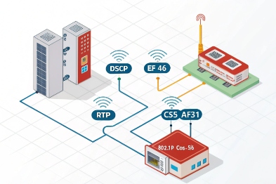
The most stable setup uses a dedicated voice VLAN, DSCP EF (46) for RTP, DSCP CS3 or AF31 for SIP signaling, and 802.1p PCP (often 5 for voice). The switch should trust markings only from known voice ports and then enforce priority queuing on uplinks.
VLAN: reduce noise and reduce broadcast risk
A voice VLAN 3 helps in three ways. It limits broadcast and multicast exposure. It simplifies access policies. It also makes troubleshooting faster because ports are predictable. Many plants already have segmented networks. Voice VLAN fits that style.
A simple voice VLAN design also lowers risk when IT and OT share links. Even if the same uplink carries many VLANs, the voice VLAN gives a clear place to apply policing and queue rules.
DSCP: mark RTP as EF, keep SIP separate
RTP should get the strongest treatment. DSCP 4 EF (46) is commonly used for real-time voice media. SIP signaling does not need EF. SIP is important, but it is low bandwidth. Many designs mark SIP as CS3 or AF31 so it stays responsive without stealing the strict voice queue.
A key detail is trust boundary. Marking is only useful when the network trusts the right devices. If every endpoint can set EF, then every endpoint can steal voice priority. That is how voice queues get congested by non-voice.
802.1p: keep L2 priority consistent
802.1p 5 PCP is helpful inside a switched LAN because it gives L2 priority even before L3 routing decisions. Many industrial switches map DSCP to PCP. A common mapping is PCP 5 for voice and PCP 3 for signaling. The exact mapping depends on the switch vendor, but the principle stays the same: consistent mapping across the path.
Queue policy: strict priority plus policing
Voice should have a strict priority queue on uplinks. Still, strict priority without policing can starve other traffic if markings are abused. A safe design uses strict priority with a bandwidth cap that matches expected voice load plus headroom.
| Item | Recommended setting | Why it helps in plants | Common mistake |
|---|---|---|---|
| Voice VLAN | Dedicated VLAN for phones | Limits broadcast and simplifies QoS | Mixing voice and cameras in one VLAN |
| RTP DSCP | EF (46) | Best queue treatment for real-time voice | Marking SIP as EF too |
| SIP DSCP | CS3 or AF31 | Keeps signaling responsive | Not marking at all |
| 802.1p | PCP 5 for voice (typical) | Preserves priority at Layer 2 | Inconsistent mapping across switches |
| Trust boundary | Trust only phone ports or voice VLAN edge | Prevents abuse and queue pollution | “Trust DSCP on all access ports” |
QoS and VLAN reduce congestion loss, but they do not fix everything. The next layer is the voice payload itself. Codec choice and jitter buffer behavior decide how well a call survives loss and jitter that still happen.
Should codecs with PLC/FEC be used, and what jitter-buffer size is optimal?
A codec choice is not only about bandwidth. It is also about how the call behaves when packets disappear or arrive late. Industrial networks do not always deliver clean timing, so the codec and jitter buffer become a safety net.
A practical plan uses packet loss concealment (PLC) by default, considers FEC only when loss patterns justify it, and prefers an adaptive jitter buffer. Start with 60–120 ms max buffer for noisy networks, then tune down if latency becomes a problem.
PLC and FEC: what they really do
PLC is the baseline. Most voice codecs use packet loss concealment 6 (PLC) to mask short loss bursts. It can repeat, interpolate, or synthesize missing audio. PLC does not recover the missing packet, but it hides the gap.
FEC 7 adds extra data so the receiver can reconstruct missing packets. FEC costs bandwidth and can add delay. FEC is useful when loss is frequent and small. It is less useful when the network drops large bursts, because FEC cannot cover long gaps without heavy overhead.
Opus, G.711, G.729: when each makes sense
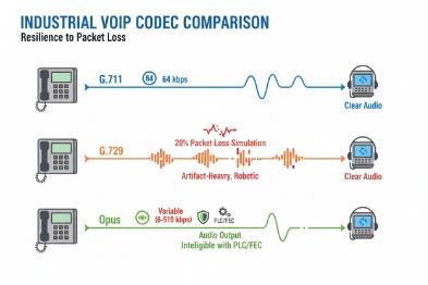
Opus 8 is flexible. It can adapt bitrate and can use built-in loss robustness options. It often works well when network conditions change. G.711 is simple and sounds natural, but it uses more bandwidth. In a clean LAN with proper QoS, G.711 is usually stable and easy. G.729 saves bandwidth, but it can sound worse and may be sensitive to transcoding paths.
For most plant LAN deployments with good QoS, G.711 is a safe baseline. For links with variable quality, Opus can be a strong option. For constrained bandwidth or satellite links, G.729 may still be used, but it needs careful planning to avoid transcoding and license surprises.
Jitter buffer: start adaptive, then tune
A fixed jitter buffer is easy, but plants are not fixed. The best practical choice is an adaptive jitter buffer 9 that grows when jitter rises and shrinks when the path is clean.
Buffer sizing depends on the site. Too small gives “loss” due to late packets. Too large adds mouth-to-ear delay. Many teams start with a target range like 30–50 ms minimum and 60–120 ms maximum in industrial networks. Then they measure RTCP jitter and late packet counts. If calls feel slow, they tune down the max. If calls break during load, they tune up.
Packetization time and burst behavior
Packetization time (ptime) matters. 20 ms ptime is common and gives a good balance. A larger ptime reduces packet rate but increases the audio gap when one packet is lost. In lossy networks, smaller ptime can make loss less painful, but it increases packet overhead. The best approach is to test with real plant traffic.
| Codec / setting | Strength | Risk | Best fit |
|---|---|---|---|
| Opus (with PLC, optional FEC) | Flexible under changing conditions | Needs careful interoperability checks | Mixed networks, variable links |
| G.711 (PLC) | High clarity, simple | Higher bandwidth | LAN with QoS and stable uplinks |
| G.729 (PLC) | Lower bandwidth | Lower quality, transcoding risk | Constrained links, managed paths |
| Adaptive jitter buffer | Handles timing variation | Adds delay when it grows | Industrial plants with bursts |
| 20 ms ptime | Balanced | Not optimal for every link | Default starting point |
Codec and buffer tuning improves survivability, but packet loss can still come from the physical layer. In hazardous zones, PoE margins, shielding, and bonding can decide if the link stays clean.
Do PoE power, shielded cabling, EMI/grounding, and monitoring tools affect RTP loss, and how can packet loss be detected fast?
A voice packet can be “lost” because a switch dropped it, but also because the phone rebooted, the link flapped, or the cable introduced errors. In hazardous areas, these issues happen more often because cable routes are long and EMI sources are strong.
Yes. PoE budget and stability prevent reboots and renegotiations that create RTP gaps. Shielded cabling and correct grounding reduce CRC errors that look like packet loss. RTCP, RTCP-XR, MOS, SNMP traps, and switch counters give early warning and point to the real fault domain.
PoE budget and power stability
A phone can stay “online” while suffering power dips. A PoE port near its limit can react poorly when temperature rises or when a long cable increases loss. A stable power budget matters more in outdoor cabinets. If the switch PSU is shared with other devices, one load spike can affect many ports.
A good practice is to size PoE 10 with margin, not with best-case numbers. The plan should include the phone’s peak draw, any heater option, and accessories like beacons. The plan should also avoid long daisy chains of PoE switches without proper upstream power.
Shielding, grounding, and EMI control reduce retransmissions and errors
RTP over UDP does not retransmit. Still, physical errors create dropped frames at the switch, and the voice stack sees loss. A switch port counter often tells the truth: CRC/FCS errors, alignment errors, and interface resets.
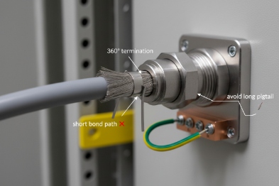
Shielded twisted pair can help when it is bonded correctly. A floating shield can act like an antenna. A poor bond can be worse than no shield. The goal is a controlled path for noise, not a random path.
Separation from high-power lines matters. Parallel runs near VFD outputs are a classic trouble source. A small routing change can cut errors dramatically. Ferrites can help in some cases, but they should not be used to hide a bonding mistake.
RTCP and RTCP-XR: measure, do not guess
RTCP reports basic metrics like packet loss fraction, jitter, and round-trip time. RTCP-XR extends reporting with more detail, like burst loss and gap loss in some implementations. These reports tell if the phone is losing packets on receive, on send, or both.
MOS is a good dashboard number, but it is an output. The inputs matter more: loss, jitter, and delay. A plant can set MOS alarms, but the response should still trace down to switch counters and path segments.
SNMP traps and switch counters: locate the fault domain fast
SNMP traps can alert on link down events, PoE power faults, and error-rate thresholds. Switch counters can show where drops happen: ingress drops, egress drops, queue drops, CRC errors, and discards. When counters rise on one uplink, the problem is usually in the path, not in the phone.
A simple workflow works well:
1) Confirm if loss is one-way or two-way using RTCP stats.
2) Check the phone port counters for CRC and link events.
3) Check the uplink queue drops and QoS counters.
4) Check PoE logs for power events.
5) Mirror traffic only after counters point to a segment.
| Signal | Where to read it | What it usually means | First action |
|---|---|---|---|
| RTP loss % rising | RTCP / phone stats | Network drops or late packets | Compare with jitter and delay |
| High jitter | RTCP | Congestion or timing variation | Check queue drops and shaping |
| Burst loss | RTCP-XR (if available) | Microbursts or link flaps | Check uplink and interface resets |
| CRC/FCS errors | Switch port counters | EMI, bad cable, poor termination | Re-terminate, reroute, bond shield |
| PoE event logs | Switch PoE logs | Power budget or PSU issue | Add margin, fix PSU, reduce load |
| Queue drops in voice class | Switch QoS counters | Voice not truly prioritized | Fix trust boundary and queue policy |
A good monitoring plan turns packet loss into a visible trend, not a surprise. It also helps maintenance teams prove the problem is in the uplink, not in the handset, not in the SIP server, and not in “the cloud.”
Conclusion
Packet loss drops when voice is isolated, marked, and queued, codecs and buffers match real jitter, physical links stay clean, and RTCP plus switch counters guide fast fixes.
Footnotes
-
RTP The protocol used to carry the actual audio data of a VoIP call across an IP network. ↩
-
SIP The signaling protocol used to set up, maintain, and terminate VoIP calls. ↩
-
VLAN A logical sub-network that groups devices together for performance and security, separating traffic types. ↩
-
DSCP A field in the IP packet header used to classify and manage network traffic priority (QoS). ↩
-
802.1p A Layer 2 quality of service mechanism that prioritizes traffic within a local area network (LAN). ↩
-
packet loss concealment Techniques used by codecs to mask the effects of missing audio packets to keep speech intelligible. ↩
-
FEC A method where redundant data is sent with the audio to allow the receiver to reconstruct lost packets. ↩
-
Opus A versatile, high-quality audio codec designed for interactive speech and music over the internet. ↩
-
jitter buffer A temporary storage area for incoming voice packets used to smooth out variations in arrival time. ↩
-
PoE Technology that passes electric power along with data on twisted pair Ethernet cabling. ↩


