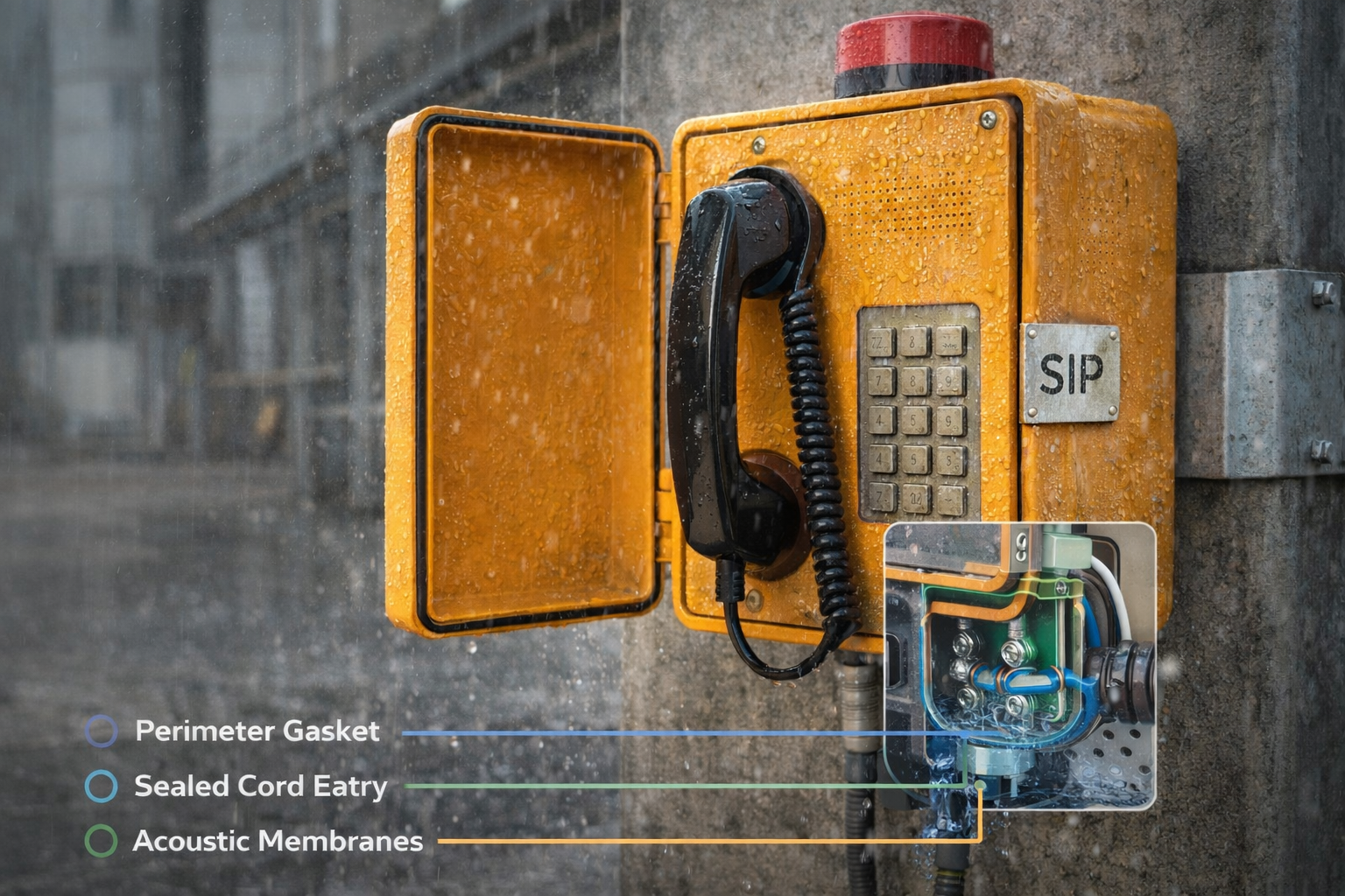
Outdoor phones often pass lab tests and still fail on site. A wrong gland size, a poor RJ45 seal, or a cut jacket can turn IP66 into a leak.
Select glands and connectors as one sealed “cable entry system”: thread and panel fit, cable OD clamp range, strain relief, shield bonding, and materials that survive UV, salt fog, and temperature.

A field-first method to spec glands and connectors without surprises
Start with the install reality, not the catalog page
A weatherproof telephone 1 usually fails at the cable entry, not the front cover. So the selection process should begin with the things the site team will actually do:
-
cable type (outdoor Cat5e/Cat6, gel-filled, armored, conduit, etc.)
-
entry direction (top/side/bottom) and whether water can sit on the entry
-
required IP level (jets vs immersion risk)
-
whether the cable must stay shielded end-to-end for EMI control
-
service approach (field-terminate vs pre-terminated)
Use one “must match” list across the whole stack
A good tender avoids vague lines like “IP67 gland.” It lists what must match:
-
enclosure wall thickness and hole/threads
-
gland clamping OD range vs your real cable jacket OD
-
strain relief target (pull, bend, and twist)
-
shield termination method (if using STP)
-
temperature range and UV/salt environment
-
acceptance proof (photos + report + assembly instructions)
A simple selection map that works on most outdoor SIP phones
| Item | Decide first | Then specify | Why it prevents failure |
|---|---|---|---|
| Thread type | Enclosure design + region | M20×1.5 or 1/2" NPT + adapter plan | Stops rework and bad hole drilling |
| Sealing | Water event | IP66 for jets, add IP67 if immersion risk | Stops “67 is always better” mistakes |
| Cable OD | Actual cable jacket OD | Clamp range that seals mid-range | Stops leaks from under/over clamping |
| EMI | EMI risk + STP use | EMC gland + 360° shield bond | Stops PoE noise and packet issues |
| Materials | UV/salt/chemicals | Nickel-brass, stainless, or UV PA66 | Stops cracking and corrosion |
| Connector style | Field service plan | IP-rated RJ45 or pigtail + sealed coupler | Stops “field RJ45” water ingress |
A short real-world lesson belongs here: many projects buy a great phone, then choose cheap glands locally. The phone fails, and the vendor gets blamed. The fix is simple: treat the gland and connector as part of the rated assembly.
Next is the first big practical question: which thread standard fits the enclosure and its thickness.
Which gland thread (M20×1.5, PG11, 1/2" NPT) fits the enclosure and panel thickness?
A wrong thread choice forces adapters, weak locknuts, or thin sealing lands. That often turns into leaks months later.
Choose the gland thread that matches your enclosure’s machining and regional supply: M20×1.5 is common for metric designs, 1/2" NPT is common in North America, and PG11 is usually a legacy choice unless you already have PG tooling.

Match thread style to how the enclosure is built
M20×1.5 (metric, straight thread)
-
Best when the enclosure uses metric hardware and you want clean, repeatable machining.
-
Works well with locknut mounting on sheet metal or cast housings.
-
Easier to standardize across products because M-series is widely used.
1/2" NPT (tapered thread)
-
Best when the enclosure is designed for NPT tapping, or when the site standard is NPT.
-
The seal depends on the tapered thread engagement and sealant method.
-
Good for thick walls where threads can be tapped directly.
PG11 (legacy straight thread)
-
Often used in older European designs and some existing panel cutouts.
-
Works fine if the tooling and supply chain are already PG-based.
-
Not the best choice for new designs unless your customer requires it.
Even with the “right” thread, panel thickness 2 can break the seal if the gland cannot seat correctly.
-
Thin panels can flex and reduce gasket compression.
-
Very thick panels can reduce usable thread engagement with a standard-length gland.
-
Powder coating thickness can change the sealing land and torque feel.
A practical approach:
-
Measure the real wall thickness at the entry, including coatings.
-
Choose a gland with a thread length that supports your thickness plus a full locknut bite.
-
If you expect both thin and thick variants (steel box vs cast box), define a long-thread gland as the default.
My default spec language for tenders
| Tender line | What it forces | Why it helps |
|---|---|---|
| “Gland thread: M20×1.5 (or 1/2" NPT) with locknut; long-thread type if panel > X mm” | Correct mechanical fit | Prevents partial thread engagement |
| “Panel hole size per gland manufacturer; no oval holes” | Clean machining | Prevents gasket creep and leaks |
| “Include sealing washer suited to coating” | Real compression | Prevents weeping around the locknut |
Quick guidance when you must support mixed regions
If the same telephone ships worldwide, the clean pattern is:
-
design the enclosure around M20×1.5
-
offer NPT adapter kits for North American projects
-
keep PG11 only when replacing an existing PG footprint
Once the thread and panel fit are correct, the next performance issue is electrical: PoE power stability and EMI control.
What cable OD range, strain relief, and shield continuity ensure PoE power and EMI control?
Many “network issues” on outdoor phones are not software problems. They are cable entry problems: jacket damage, poor strain relief, or broken shield bonding.
For PoE and EMI control, clamp the gland on the cable jacket within the correct OD range, build real strain relief inside the enclosure, and use a 360° shield termination method when STP is required.
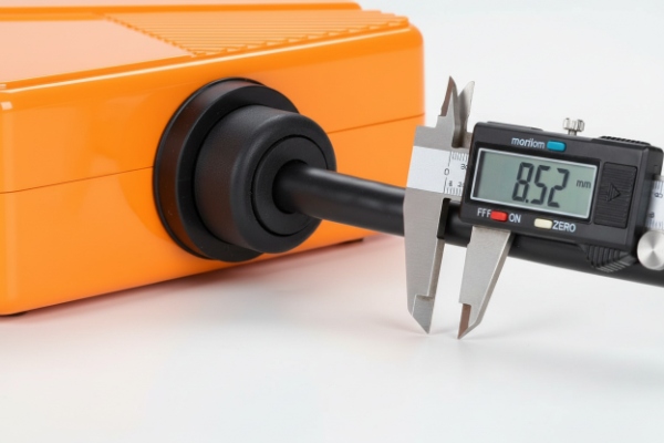
Cable OD: pick the clamping range from your real cable, not a guess
Outdoor Cat5e/Cat6 cables vary a lot in jacket OD, especially if they are gel-filled, armored, or have thick PE jackets.
-
Measure OD on several cable samples, including cold-condition samples if possible.
-
Choose a gland insert that seals when the cable sits near the middle of the clamping range.
-
Avoid “barely fits” selections. That is where jackets get cut and seals creep.
Strain relief: the gland is not enough
A gland seals. It does not fully protect against repeated pulling, twisting, and handset cord movement.
Good practice inside the phone:
-
add a cable clamp or tie-down point within 50–100 mm of the entry
-
keep a safe bend radius (tight bends hurt PoE and data)
-
avoid cable weight hanging on the RJ45 or PCB header
If the phone is pole-mounted, add a drip strategy:
-
route cable downward before entry
-
add a drip loop if the entry is on the side
-
avoid top entry unless you have a hood and strong gland protection
Shield continuity: decide your EMC strategy early
For EMI control 3, the question is not “shielded or unshielded.” The question is “where does the shield bond?”
-
If the project uses STP and wants real shielding, use an EMC cable gland that provides 360° braid contact to the metal enclosure at the entry.
-
Keep the shield path short and wide. A long drain wire loop is a weak shield at high frequency.
-
Bonding style should match the system grounding plan. Many sites prefer bonding at the equipment end, but large installations often use multi-point bonding for noise control. The key is consistency.
A table that ties mechanics to PoE stability
| Problem seen on site | Root cause | Spec fix |
|---|---|---|
| Random reboots under load | Cable jacket cut, water ingress, or loose pairs | Proper clamp range + IP rating + strain relief |
| Weak PoE at far end | High resistance from poor terminations | Use correct connectors + limit run length + verify pair integrity |
| EMI noise / packet loss | Floating shield or poor bonding | EMC gland + 360° termination + correct grounding |
| Corrosion at entry | Wrong material or salt exposure | Nickel-brass/stainless + anti-corrosion design |
Now we move to materials. This is where outdoor projects differ a lot. Some sites are mild. Some sites destroy plastics in two summers and corrode brass in a year.
Do materials and ratings—PA66 or nickel-brass, IP66/IP67, UL 94 V-0, UV/salt-fog—meet site needs?
Many tenders list these items as buzzwords. The better way is to connect each requirement to a real failure mode.
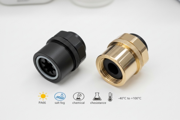
Use UV-stabilized PA66 for cost and weight when the site is mild, choose nickel-plated brass or stainless for harsh mechanical and salt environments, and match IP66/IP67 to the water event. Add UL 94 V-0 when fire performance is required by the project.
Material choice: PA66 vs nickel-brass vs stainless
PA66 (nylon)
-
Works well when it is UV-stabilized and the site is not extreme.
-
Lighter and often lower cost.
-
Best for controlled outdoor sites where mechanical abuse is limited.
Risk to watch:
-
poor UV grades can embrittle
-
some chemicals and oils can reduce life
-
threads can be easier to damage if over-torqued
Nickel-plated brass
-
Strong mechanical performance.
-
Better thread durability.
-
Often a solid default for industrial outdoor sites.
Risk to watch:
- in severe marine or chemical mist, corrosion can still happen over time, especially if plating is damaged
Stainless (often used in severe sites)
-
Best where salt fog, chemical mist, and long life are critical.
-
Useful when the project is coastal, offshore, or near strong cleaners.
The clean approach is to define “site class” in the tender:
-
mild outdoor → UV PA66 is acceptable
-
industrial outdoor → nickel-brass is preferred
-
marine/chemical → stainless is preferred
IP66 vs IP67: specify both only when you truly need both
-
IP66 fits strong rain and water jets. It is the normal outdoor target for cleaning and storms.
-
IP67 fits temporary immersion risk, like low mounting near drainage or flood events.
If your site uses hose jets and also has flooding risk, ask for IP66 + IP67 evidence. Do not assume IP67 covers jets.
UL 94 V-0: when it matters
UL 94 V-0 4 is mainly relevant when:
-
the customer requires it for plastic parts
-
the installation is in regulated environments
-
the tender is aligned with a wider UL compliance package
If your gland is metal, UL 94 is not the key decision. If your gland is PA66, UL 94 V-0 can be a useful requirement when the project calls for it.
UV and salt-fog: make them testable
Instead of writing “UV resistant” as a vague line, define it:
-
“UV-stabilized material suitable for outdoor exposure”
-
“Salt-fog resistant hardware for coastal sites”
-
“No cracking, no major corrosion that affects sealing after exposure”
This keeps the vendor honest and reduces debate during acceptance.
Now we get into the connector side. Field RJ45 is where many outdoor SIP installs struggle, especially in cold climates and long runs.
How should RJ45 field connectors and gel-filled outdoor cable be sized for −40–70°C and long runs?
Outdoor Ethernet fails because installers treat it like indoor Ethernet. Cold makes jackets stiff. Water pushes into crimps. Long runs increase PoE drop. Then the phone “works in the lab” and fails in winter.
For −40–70°C and long outdoor runs, use IP-rated RJ45 solutions sized to your cable OD, prefer PE-jacket outdoor cable (often gel-filled for water blocking), and plan the network so Ethernet stays within distance limits or use mid-span switches/fiber where needed.
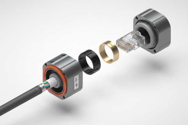
RJ45: decide between “sealed coupler” vs “pigtail”
Two patterns tend to work best:
Option A: Sealed gland + internal RJ45 (pigtail inside)
-
The installer brings raw cable through a gland.
-
Termination happens inside a protected chamber.
-
Risk is reduced because the RJ45 is not exposed to rain.
This is often the most reliable design for weatherproof telephones.
Option B: IP-rated field RJ45 connector or sealed RJ45 coupler
-
Useful when the project needs fast swap and modular service.
-
The connector must match the cable OD and jacket type.
-
Cold temperature rating must match your site.
In harsh climates, a sealed coupler with the wrong OD range is a common failure. It feels tight, but it does not seal the jacket correctly.
Cable sizing for temperature and water
For −40–70°C projects:
-
prefer PE jacket outdoor cable (more stable in weather than common indoor PVC)
-
confirm cold bend behavior so installers do not crack the jacket
-
use gel-filled or water-blocking designs for long outdoor runs, especially direct burial or wet conduit
Gel-filled cable 5 helps because water can migrate inside conduit over time. If the cable has no water block, moisture can travel and cause corrosion at terminations.
Long runs: plan PoE drop and network topology
Ethernet channel length is limited in practice. Long cable also increases voltage drop for PoE, especially at higher power classes.
A stable plan for long runs:
-
keep copper segments within normal Ethernet limits
-
use an intermediate switch, PoE extender, or move to fiber for long distances 6
-
place PoE power closer to the device when runs are near the limit
A small but important practice:
- keep termination quality high. Poor terminations add resistance and can cause PoE brownouts.
A table for sizing and tender wording
| Item | What to specify | Why it matters at −40–70°C |
|---|---|---|
| RJ45 field connector | IP-rated type, OD range, shielded/unshielded match | Stops leaks and mismatch in cold |
| Cable jacket | Outdoor PE jacket, UV rated, water-block/gel if needed | Prevents cracking and water migration |
| Temperature | Rated components −40 to +70°C | Avoids stiff seals and brittle plastics |
| Shielding | STP end-to-end if EMI needs it | Prevents noise and link drops |
| Strain relief | Clamp + bend radius control | Stops jacket damage and conductor pull |
A simple way to explain this to clients
-
“Outdoor RJ45 is not the same as indoor RJ45.”
-
“The connector must match the cable OD and jacket.”
-
“Cold makes everything stiffer, so sealing margins shrink.”
-
“Long runs need network planning, not hope.”
Conclusion
Choose glands and connectors as one system: correct thread and panel fit, correct OD clamp and strain relief, real shield bonding, and materials rated for your sun, salt, and temperature.
Footnotes
-
Rugged communication device designed to operate reliably in harsh outdoor environments. [↩] ↩
-
The material depth of the enclosure wall where the cable gland is mounted. [↩] ↩
-
Practices to manage electromagnetic interference and ensure signal integrity. [↩] ↩
-
Flammability standard indicating plastic stops burning within 10 seconds on a vertical specimen. [↩] ↩
-
Outdoor cable with a water-blocking compound to prevent moisture migration. [↩] ↩
-
Device that boosts Ethernet signals and PoE power beyond standard distance limits. [↩] ↩


