A refinery phone can look “installed” but still fail when the PLC never sees the SOS signal. That gap can delay response when seconds matter.
Wire it like a control loop, not like a speaker: use the phone’s certified relay terminals (COM/NO/NC), match your PLC DI type (PNP/NPN), and keep Ex integrity by using approved glands, barriers where needed, and documented logic.

The safe way to think about PLC wiring in hazardous areas
Treat Ex compliance as the first constraint
An explosion-proof telephone may use Ex d, Ex e, or a combined concept (for example, Ex d enclosure with an Ex e terminal chamber) as defined in the IEC 60079 series 1. That matters because the wiring rules are not “DIY electrical.” The rule is simple: use only the provided certified terminal points, keep the enclosure and flamepaths untouched, and use only approved cable entries and glands. If a site drills extra holes or swaps a gland to a non-certified type, the Ex design can be compromised.
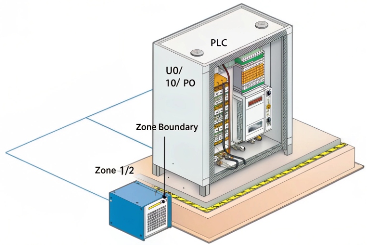
A PLC dry contact link sounds harmless because it is “just a contact.” Still, the loop is real electrical energy. The loop runs through a hazardous area, through a gland, and into a terminal chamber. This is why the wiring method must match the protection concept and the area classification (often governed by frameworks like the ATEX Directive 2014/34/EU 2). Many sites use two acceptable patterns:
- Non-intrinsically safe (non-IS) control loop, routed and protected per hazardous-area wiring rules, using the phone’s certified terminals and a certified gland.
- Intrinsically safe (Ex i) loop, using a barrier or galvanic isolator near the PLC cabinet, so the field wiring stays energy-limited.
The right choice depends on the phone certificate and the plant philosophy. Many offshore and refinery owners prefer Ex i for signals because it makes maintenance easier and reduces risk during troubleshooting. Other sites keep it non-IS because the phone is Ex d and the loop does not switch outside the enclosure.
Start by identifying what the phone actually provides
Explosion-proof telephones typically offer one or more of these outputs:
- Dry relay contact: COM, NO, NC (potential-free)
- Open collector / transistor output (less common on Ex phones)
- Input terminals: for external buttons, door contact, beacon trigger, etc.
For PLC integration, the relay is the most common because it is simple and immune to noise. The PLC input side can be:
- PNP (sourcing) DI: expects +24 V at DI relative to 0 V
- NPN (sinking) DI: expects DI pulled to 0 V with +24 V present
- AC DI (rare for modern instrumentation loops)
If the PLC input type is unknown, do not guess—review a PNP/NPN (sourcing/sinking) input wiring guide 3 and confirm the DI common on the actual card. A wrong assumption causes “always on” alarms, floating inputs, and random chatter.
| Item to confirm before wiring | Why it matters | What to record in the panel drawing |
|---|---|---|
| Phone I/O type (relay vs transistor) | Changes wiring and barrier choice | Terminal names and ratings |
| Contact rating (V/A) | Prevents welding or nuisance faults | Max V, max A, load type |
| PLC DI type (PNP/NPN) | Decides where COM/NO/NC goes | DI common reference |
| Hazardous area classification | Drives IS vs non-IS decision | Zone/Div and gas group |
| Certificate constraints | Prevents invalid installation | Allowed glands and cable types |
A clean plan saves time later. It also makes FAT and commissioning smoother because every test has a defined expected result.
Next, the wiring becomes straightforward when terminal naming and Ex constraints are respected.
This is where most mistakes happen: not at the PLC, but at the terminal choice and the cable entry.
Which terminals connect for PLC DI/DO—NO/NC, COM, and 24 V—without violating Ex d/e requirements?
Bad wiring often comes from mixing “dry contact” and “powered input” in the same sentence. The contact is dry. The PLC loop is powered.
Use the phone relay terminals as a switch in the PLC DI loop: wire PLC +24 V through COM→NO (or COM→NC) into the DI, and keep all field terminations inside the certified terminal compartment using certified glands and cable OD matching.
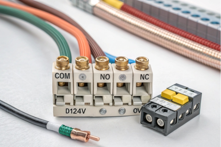
The basic concept: the phone relay only switches the loop
Most PLC DI modules provide a 24 V supply (internal or external). The DI “turns on” when it sees voltage or current in the expected direction. The phone relay should never be fed from an unknown supply and should never be used to carry loads like beacons or sirens unless the relay rating and Ex method allow it. Use it as a signal, then drive outputs from the PLC side.
Two common wiring options exist.
Option A: Switch +24 V into the DI (typical PNP style)
- PLC +24 V → Phone COM
- Phone NO → PLC DI channel
- PLC DI common → PLC 0 V (as required by the module)
Option B: Switch DI to 0 V (typical NPN style)
- PLC DI channel has pull-up to +24 V
- Phone COM → PLC 0 V
- Phone NO → PLC DI channel
If you want fail-safe behavior, use NC and invert the logic in the PLC (more on that later).
Practical wiring diagrams (field-friendly)
These are simplified. The PLC module manual still wins.
PNP-style “contact makes DI high”
- +24 VDC (from PLC PSU) → COM (phone relay)
- NO (phone relay) → DIx (PLC input)
- 0 VDC → DI common (PLC)
Fail-safe PNP using NC
- +24 VDC → COM
- NC → DIx
- 0 VDC → DI common
Now a broken wire or power loss tends to create a DI change that the PLC can treat as alarm.
Do not violate Ex d/e installation rules
On an Ex d phone, the “explosion-proof” part is often the main enclosure. The terminal chamber may be Ex e (increased safety) or also within Ex d, depending on design. The safe behavior is the same:
- Terminate cables only at the provided terminals.
- Use certified Ex glands of the correct type (Ex d/e as required), correct thread, and correct sealing range for the cable OD.
- Do not add extra junction boxes unless they are also certified for the zone.
- Maintain the correct cover torque and gasket seating per the manual.
- Do not open the enclosure when energized in hazardous areas unless procedures allow and the protection concept supports it.
| Terminal choice | Best use | Common wiring mistake | Better practice |
|---|---|---|---|
| COM + NO | “Event makes input ON” | Feeding unknown voltage into phone | Use PLC 24 V only, document source |
| COM + NC | Fail-safe supervision | Forgetting to invert logic | Invert in PLC, alarm on open |
| 24 V terminal on phone (if exists) | Powering phone I/O features | Mixing with DI supply | Keep phone power and PLC DI separate |
| Shield/earth terminal | EMC and bonding | Floating shield at field end | Follow one approved bonding method |
Once the terminals are correct, the next decision is whether the loop should be intrinsically safe. That decision changes the hardware around the PLC cabinet.
Should an isolator or Ex i barrier be used between PLC input and phone relay?
Many plants argue about this because both sides are partly correct. The best answer depends on the certificate and the site’s maintenance philosophy.
Use a barrier or galvanic isolator when you want an Ex i signal circuit, when the certificate requires it for external I/O, or when cable routing and maintenance conditions make energy-limited wiring the safest and easiest option.
When a barrier is strongly recommended
A barrier (Zener) or galvanic isolator is usually the right choice when:
- The phone I/O wiring runs long distances on exposed trays.
- The plant requires all field signals in a given zone to be Ex i.
- The wiring passes through mixed areas and maintenance teams want “live work” capability.
- The phone certificate lists “entity parameters” or requires IS interface for certain terminals.
- The PLC DI card is high sensitivity and noise causes chatter.
A galvanic isolator is often preferred over a simple Zener barrier in modern projects because it does not rely on a high-integrity earth the same way, and it provides isolation that helps EMC—see intrinsic safety isolated barriers 4.
When a barrier may be optional
A barrier may be optional when:
- The phone terminals are part of an Ex d concept and the external loop is not required to be IS by the project standard.
- The loop carries only low energy and is routed per hazardous-area wiring rules.
- The site already has proven practice using non-IS control loops in that zone.
Still, “optional” does not mean “ignore.” The decision must be written in the project method statement.
How to wire with a barrier using a dry contact
For a dry contact, the barrier or isolator typically sits near the PLC cabinet. The field wiring from the barrier to the phone is the IS side. The dry contact simply opens/closes the IS loop.
A common pattern is:
- IS supply/output from isolator → field loop → phone COM/NO → return to isolator input channel
or - isolator provides a sensing input that detects open/closed contact in the field
The exact wiring depends on the isolator type. The goal stays the same: the energy in the hazardous area stays below ignition-capable levels.
| Approach | Pros | Cons | Best fit |
|---|---|---|---|
| No barrier (non-IS) | Simple, low cost | Harder maintenance rules, more routing constraints | Sheltered modules with strict controls |
| Zener barrier | Cost-effective | Needs high-quality earth and careful design | Sites with strong barrier standards |
| Galvanic isolator | Isolation, better EMC, easier grounding | Higher cost | Offshore, FPSO, wind farms, mixed EMC zones |
In offshore and wind farm projects, the isolator approach often reduces commissioning headaches. It also reduces the chance that a troubleshooting mistake creates a non-compliant situation.
After hardware decisions, the next piece is logic. A good wiring job still fails if the PLC logic treats bounce and broken wires the wrong way.
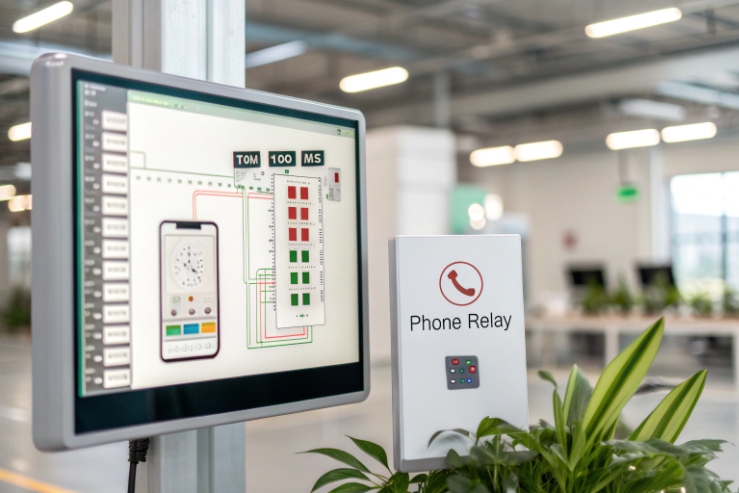
How to program signal logic—off-hook, SOS, or fault—to PLC with debounce and fail-safe?
A relay contact can look clean on a meter and still produce a noisy signal in a PLC scan. Bounce and short transients can create false alarms.
Map each phone event to one PLC tag, then use debounce timers, edge detection, and fail-safe contact selection (often NC) so broken wires and power loss create a safe alarm state.
Decide what the contact means: momentary, maintained, or pulse
Explosion-proof phones usually support a few event styles:
- SOS pressed: can be a pulse, a maintained output until reset, or a call state
- Off-hook: maintained while handset lifted
- Fault: maintained when device reports a fault (network, power, self-test)
Match the PLC logic to the event style. A pulse event needs edge detection and latching. A maintained event needs state monitoring and supervision.
Debounce in PLC: simple and effective
Debounce is a timer filter that ignores rapid changes. Two common strategies work well (and the underlying physics is classic switch/relay contact bounce and debounce techniques 5):
Strategy 1: On-delay confirmation
- Input must remain ON for X ms before you accept it.
- Use 50–200 ms for relay bounce.
- Use longer (300–800 ms) if long cables pick up noise.
Strategy 2: Change-of-state with deadband
- After the input changes, ignore further changes for X ms.
For SOS, a latching alarm is usually best:
- Detect rising edge of SOS input.
- Latch an “SOS_Alarm” bit.
- Require a deliberate reset action from HMI or a supervisor key.
Fail-safe: use NC when supervision matters
If a phone SOS must be supervised, wire the relay using NC so that:
- Normal healthy state keeps the input ON (or OFF, depending on wiring).
- Broken wire, loose terminal, or power loss changes the input to alarm.
This gives you a “line break” behavior without extra hardware.
| Event type | Best relay contact choice | PLC logic pattern | Operator experience |
|---|---|---|---|
| SOS emergency | NC (fail-safe) or NO (simple) | Edge detect + latch + manual reset | Clear alarm that stays until cleared |
| Off-hook | NO (maintained) | Debounce + state timer | Shows phone in use |
| Phone fault | NC (fail-safe) | Debounce + alarm after delay | Detects power/network loss early |
| Test call / maintenance | NO | Latch only during maintenance window | Avoids nuisance alarms |
Add “reason codes” if you can
A single dry contact cannot carry rich details. Still, the PLC can create useful reason codes by combining:
- Phone contact state
- Time-of-day schedule
- Network switch port link status (from managed switch or SCADA)
- Power/UPS status
This turns one contact into a better operational signal, especially offshore where maintenance teams rotate.
Once the logic is correct, the final risk is physical: cable entry, grounding, and EMC. This is where most IP66/67 and “random DI chatter” problems come from.
What cable, gland, and grounding practices ensure IP66/67 and EMC when linking to PLC cabinets?
A perfect wiring diagram still fails if the gland leaks or the cable shield floats. Offshore and refinery EMC can be brutal near VFDs and radio systems.
Use a shielded twisted pair (or shielded multi-core) with a certified gland matched to cable OD, keep 360° shield termination where required, and bond the enclosure to the equipotential network while separating signal cables from high-noise power runs.
Cable selection: choose by environment, not only voltage
For a dry contact loop, electrical load is small, but mechanical and chemical stress is large. Good practices include:
- Use industrial control cable with oil and UV resistant jacket if outdoors.
- Use shielded twisted pair for long runs or high EMI zones.
- Use armored cable when mechanical damage risk exists on trays or decks.
- Keep conductor size reasonable (often 0.5–1.5 mm² range) so terminations stay stable.
Avoid mixing this loop inside the same multi-core as VFD outputs or high-current motor feeders.
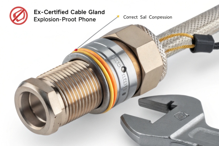
Glands: the most common IP failure point
To maintain IP66/67 per IEC IP ratings 6, the gland must match:
- hazardous-area certification type (Ex d / Ex e / Ex i as required)
- thread type and size (M20/M25/NPT, as specified)
- cable outer diameter sealing range
- armor termination method (if armored cable)
- material compatibility (316L or marine-grade where salt is present)
When selecting barrier vs compression glands for Ex d/e entries, use the IEC 60079-14 cable gland requirements paper 7 as a practical checklist.
A wrong gland can pass an initial hose test and still leak after vibration and thermal cycling. Tighten glands to specified torque and use correct sealing washers if required.
Grounding and shielding: one approved method, no improvisation
For EMC, the goal is to control where noise currents flow. The common approach for shields is:
- Bond the shield at the cabinet end to a clean EMC earth bar.
- Bond the phone enclosure to the local equipotential bonding network.
- If the site uses 360° shield bonding at both ends, follow that consistently and document it. Mixed bonding rules create unpredictable noise.
For long cable runs in offshore zones, 360° termination at the gland can be valuable. It reduces high-frequency coupling. Still, it must match the Ex method and the site grounding philosophy.
Practical routing rules that reduce nuisance alarms
- Keep signal cables at distance from power cables, especially VFD outputs.
- Cross power cables at 90° if they must cross.
- Use separate trays or separators in shared trays.
- Add ferrites or common-mode suppression in the cabinet only if needed and approved.
| Field issue | Likely root cause | Fix that usually works |
|---|---|---|
| Random DI chatter | EMI pickup, floating shield, long parallel routing | Shielded pair, proper bonding, reroute away from VFD |
| Water ingress at phone | Wrong gland OD, poor torque, damaged jacket | Correct gland, strain relief, replace damaged section |
| Corrosion at gland | Wrong material for salt exposure | 316L gland, protect threads, match washers |
| “Stuck alarm” after rain | Gland leak causing terminal contamination | Clean terminals, retest IP, improve sealing |
| False SOS during radio use | Poor shielding or bonding | 360° shield termination, equipotential bonding review |
A final practical tip: treat the PLC cabinet end as the “control point.” Put your barrier/isolator, surge protection (if used), and shield bonding there. Keep the field end simple and sealed.
Conclusion
Wire the phone relay as a switch in the PLC DI loop, keep Ex integrity with certified terminals and glands, add barriers when the project demands Ex i, and use debounce plus fail-safe logic to stop false alarms.
Footnotes
-
IECEx list of IEC 60079 standards for Ex d/e/i protection concepts. ↩ ↩
-
Read the official ATEX Directive 2014/34/EU text and applicability for equipment in explosive atmospheres. ↩ ↩
-
Quick guide explaining PNP/NPN (sourcing/sinking) wiring so you match PLC input commons correctly. ↩ ↩
-
Overview of intrinsic safety isolated barriers and galvanic isolation options for field signals in hazardous areas. ↩ ↩
-
Practical explanation of switch/relay contact bounce and debounce techniques for cleaner PLC inputs. ↩ ↩
-
IEC explainer for IP ratings (IEC 60529), including what IP66 and IP67 test conditions mean. ↩ ↩
-
IEC paper summarizing IEC 60079-14 cable gland requirements and when barrier glands are needed for Ex d. ↩ ↩


