A hazardous-area SIP phone can carry power, data, and accessories. One wrong interface can turn a certified device into a field risk and an audit failure.
Yes. An Ex d + Ex i combination is feasible for explosion-proof telephones. Ex d contains ignition-capable parts, and Ex i limits energy on selected circuits that leave the enclosure or touch user-accessible accessories.

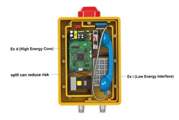
Ex d + Ex i is a design pattern, not a shortcut
What the combination really means
Ex d 1 (flameproof) is a containment method. It assumes something inside can ignite a gas mixture. The enclosure must survive that internal explosion and stop flame transmission through its joints and entries. Ex i 2 (intrinsic safety) is an energy-limiting method. It assumes the circuit can be exposed to the explosive atmosphere, and it keeps sparks and heating below ignition limits.
A d+i telephone uses both ideas at the same time. The high-energy parts stay inside Ex d. The circuits that must pass through interfaces, like a handset cord or accessory port, are designed as Ex i. This split can reduce risk because the user and the installer handle IS interfaces more safely than flameproof joints.
Why SIP phones often need the split
SIP phones have parts that do not fit Ex i very well. PoE 3 and Ethernet links can carry power and transient energy that usually exceed IS limits. Audio amplifiers and ringers can also exceed IS limits. Ex d is a practical way to keep these functions. At the same time, a handset, a headset jack, or a dry-contact alarm input is easier to manage with Ex i, because those interfaces are touched, replaced, and routed in the field.
What this approach does not do
Ex i circuits do not “cancel” Ex d requirements. Any penetration through an Ex d wall still needs certified flameproof integrity. The d+i approach mainly changes the rules for the circuits and accessories on the outside of the phone. It does not let anyone use random glands, random feedthroughs, or random wiring methods.
| Design option | What it protects best | What it complicates | Best-fit use on telephones |
|---|---|---|---|
| Pure Ex d | High-energy electronics in Zone 1 | Installation and servicing can touch flamepaths | Rugged SIP phones with standard I/O |
| Pure Ex i | User interfaces and low-power devices | Limits power, features, and cabling | Low-power, feature-light phones or terminals |
| Ex d + Ex i | High-energy core + safer external interfaces | Needs strict segregation and clear documentation | SIP phones with accessory ports, alarms, or replaceable handsets |
A d+i telephone is strongest when the supplier treats it as a system. The certificate, the nameplate, the wiring layout, and the accessory list must match. If any one part is vague, the site ends up guessing, and guessing is where Ex compliance breaks.
A good decision comes next: when should Ex i circuits be used together with Ex d in a SIP telephone, and when is it just extra complexity?
When should Ex i circuits be used together with an Ex d enclosure in hazardous-area SIP phones?
If the phone has a flameproof body, it is tempting to keep everything inside Ex d and call it done. That choice often creates hard field work and higher error rates.
Use Ex i circuits with an Ex d SIP phone when the design includes user-accessible or field-accessory interfaces that must be safe to touch, replace, and route without opening the flameproof enclosure or managing high-energy wiring at the edge of the device.

Use Ex d for the “power and data core”
A SIP phone core usually includes PoE/DC input conditioning, Ethernet PHY circuitry, audio power stages, and surge protection. These blocks are hard to make intrinsically safe while keeping normal SIP performance and loudness. Ex d is a practical home for those parts in Zone 1 and Zone 2.
Use Ex i for interfaces that people touch and swap
Ex i is most useful on a telephone when the interface is:
-
physically exposed, like a handset cord or headset socket,
-
replaceable, like external alarm accessories or add-on modules,
-
routed through cable trays and junctions where mistakes happen.
A handset and cord are good examples. The handset itself can be treated as “simple” from an ignition standpoint only if the circuit feeding it is energy-limited and the connected parts are controlled. A similar logic applies to headsets and external beacons or sounders that may be powered from the phone or triggered by it.
Use Ex i when the site wants a safer service routine
Many sites do not want technicians opening flameproof covers during normal work. A d+i phone can keep the Ex d enclosure closed while still allowing safe checks on IS accessory circuits. This matters when phones are in high-traffic areas and service work must be fast.
| Phone interface | Typical risk | Why Ex i helps | Common design choice |
|---|---|---|---|
| Handset cord + handset | Field replacement, cord damage | Limits energy at the cord | IS audio path with controlled parameters |
| Headset port | Plug/unplug events, mixed accessories | Keeps port energy low | IS headset interface or “allowed list” |
| External alarm input | Long field wiring, induced energy | Predictable entity limits | IS input loop with Co/Lo limits |
| External alarm output | Loads vary, wiring errors | Requires strict limits | IS open-collector or IS relay interface |
| Ethernet/PoE | High energy and transients | Usually not IS | Kept inside Ex d with certified entry |
The key is to apply Ex i only where it reduces real field risk. If a port will never be used, adding Ex i can add paperwork without adding safety. A clean d+i design clearly shows which terminals are intrinsically safe and which are not, and it keeps installers from mixing them.
Once Ex i circuits exist, the design must respect intrinsic safety parameters. Those parameters place hard limits on handset, keypad, headset, and alarm accessories.
How do intrinsic safety parameters (Uo/Io/Po, Co/Lo) limit handset, keypad, headset, and external alarm accessories?
Accessory selection is where d+i phones get into trouble. Teams buy a “compatible” headset or alarm beacon, then discover the entity limits do not match and the circuit is no longer compliant.
Intrinsic safety parameters limit accessories by setting maximum source output (Uo/Io/Po) and maximum allowed external stored energy (Co/Lo). The handset, headset, and alarm accessories must fit within those limits after cable capacitance and inductance are included.

Think in two halves: source limits and loop limits
Most IS circuits are verified with an entity concept. The “source” side lists:
-
Uo (open-circuit voltage),
-
Io (short-circuit current),
-
Po (maximum output power).
The “load” side lists the device input limits:
-
Ui, Ii, Pi for powered IS apparatus, or
-
Ci, Li for simple apparatus and passive parts.
Then the cable adds capacitance and inductance. The circuit stays compliant only when the external device plus cable stays within the allowed Co and Lo values stated for that IS output.
How this hits common telephone accessories
-
Handset and cord: The handset transducer and cord add capacitance and inductance. A long or different cord can break the allowed Co/Lo. A “looks identical” handset can still fail because its Ci/Li differs.
-
Headset: Headsets vary widely. Some have active electronics. Some are passive. Active headsets can exceed Ui/Ii/Pi assumptions. Passive headsets can still violate Co/Lo with long cords.
-
Keypad: The keypad is usually inside the phone. It is often not an external IS loop. The risk appears when a design offers external keypad modules or remote buttons. Those become IS accessories and must match the entity limits.
-
External alarms: A beacon or sounder can draw too much power for Ex i. Many “alarm outputs” on IS devices are not power outputs at all. They are IS signal outputs that require an IS-rated external driver.
A practical procurement method that avoids bad substitutions
1) Ask the supplier for the IS circuit table in the certificate or control drawing. It should list Uo/Io/Po and Co/Lo for each IS interface.
2) Ask for the allowed accessory list or the accessory entity values (Ui/Ii/Pi, Ci/Li).
3) Add the cable values for the planned routing and include the handset curly cord as a real cable.
4) Reject any accessory that needs more voltage, current, or power than the IS output can provide.
5) Reject any accessory plus cable that exceeds Co or Lo.
| Accessory | What usually limits it | What to request from the supplier | Common failure |
|---|---|---|---|
| Handset + curly cord | Co/Lo margin is small | Approved handset PN and cord type | “Aftermarket” handset breaks entity limits |
| Headset | Ui/Ii/Pi if active, Co/Lo if passive | Approved headset list or entity data | Plugging a consumer headset into an IS port |
| Remote call button | Cable C/L dominates | Max cable length rules | Too-long cable exceeds Co/Lo |
| External alarm beacon | Power demand exceeds Po | Clarify “signal vs power” output | Trying to power a beacon from an IS output |
This is where a d+i design can be very clean. The supplier can lock down accessories and make site work safer. It can also be very messy if the supplier does not publish the entity parameters and allowed accessories in a clear document.
Once the parameters are set, compliance inside the phone depends on segregation, spacing, and grounding practices. Ex i is sensitive to wiring discipline, even when an Ex d enclosure is used.
What wiring segregation, creepage/clearance, and earthing practices keep Ex i circuits compliant inside an Ex d telephone design?
Many people assume an Ex d enclosure makes internal wiring “safe by default.” That is not true for intrinsic safety. Ex i depends on controlled separation and predictable fault behavior.
Keep Ex i compliance inside an Ex d telephone by segregating IS and non-IS circuits, maintaining required spacing and insulation coordination for IS parts, using clear identification, and applying earthing rules that match the chosen barrier or isolator method.

Segregate circuits like they can touch during faults
Inside a telephone, vibration, heat, and service work can shift wires. The design should assume wires can move unless they are fixed. A strong d+i layout uses:
-
separate terminal groups for IS and non-IS,
-
physical partitions or dedicated wiring channels,
-
short and protected IS routing from the barrier/isolator to the IS terminal,
-
clear “IS” identification on wires, terminals, and drawings.
Even in a flameproof body, mixing IS and non-IS conductors in the same harness without control increases the chance of an energy transfer fault. That fault can break the IS assumptions.
Treat feedthroughs and terminations as Ex-critical parts
If an IS circuit leaves the phone, it still needs a controlled path through the enclosure. A good design uses a certified bushing, a potted feedthrough, or a flameproof cable entry arrangement that preserves Ex d integrity. The internal termination should also prevent stray strands and loose screws, because a loose termination can create heat and can also defeat segregation.
Earthing and shielding: choose a method and document it
IS systems can use Zener barriers 4 or galvanic isolators. Zener barriers typically depend on a reliable earth reference. Galvanic isolators reduce reliance on a single earth point, but they still need bonding and EMC 5 control. In telephones, shielding is also tied to audio quality and surge behavior. The safe practice is to document:
-
where cable screens are bonded,
-
whether screens are bonded at one end or both ends,
-
how the Ex d housing and mounting bracket are bonded to PE,
-
how the IS reference is treated.
| Practice | Why it matters | What goes wrong in the field | Control that works |
|---|---|---|---|
| Physical separation of IS wiring | Prevents energy transfer faults | IS and non-IS tied together with zip ties | Dedicated duct or partition for IS |
| Clear identification (blue/labels) | Prevents wrong termination | IS loop landed on non-IS terminal | Label terminals and drawings, train installers |
| Secure terminations and strain relief | Stops heat and movement | Loose strands, hot terminals | Torque control and pull test |
| Defined screen bonding | Controls EMC without breaking IS | Screen tied wrong, noise and faults | One documented bonding scheme |
| Robust enclosure bonding | Controls fault currents | Floating metal parts | External earth stud + internal bonding |
A d+i telephone can be very reliable, but only when the wiring rules are built into the mechanical design. If compliance depends on “installer skill,” the design will fail sooner or later.
The last step is verification. A d+i architecture must be visible in the certificate and the marking. If the marking is vague, procurement cannot defend the selection, and the installer cannot wire it correctly.
What certificates and Ex markings must confirm a d+i architecture, including protection concepts, EPL, gas group, T-class, and “X” conditions?
A “d+i” claim is real only when the marking and certificate show both concepts and define the limits for the intrinsically safe circuits.
Certificates and nameplates must show the combined protection concepts, the intended EPL, gas group, and T-class, plus defined IS entity parameters for each IS circuit. Any “X” suffix must be supported by written special conditions that control glands, accessories, and wiring methods.

Nameplate markings that indicate a combined concept
A combined marking often shows Ex d plus a bracketed Ex i part for the IS circuits. The bracket indicates the IS circuit rating inside the overall apparatus. A typical pattern looks like:
- Ex db [ib] IIC T6 Gb
or, when IS circuits are rated for a higher EPL than the overall apparatus:
- Ex db [ia Ga] IIC T6 Gb
If the phone is also dust-rated, it should show a separate dust marking line, such as:
- Ex tb IIIC T85°C Db
The gas line uses a T-class 6. The dust line uses a °C surface temperature limit. Both must be present if the product claims both hazards.
Certificate items that must exist for a true d+i telephone
A certificate package for d+i should include:
-
the marking line exactly as shown on the nameplate,
-
the standards list used for assessment,
-
the entity parameters for each IS circuit (Uo/Io/Po and Co/Lo),
-
any limitations on cable types, cable lengths, and approved accessories,
-
the ambient temperature range (Ta) if it constrains use,
-
drawings or a control document that shows terminal labeling and segregation method.
Treat “X” and “U” as hard filters
-
“X” means Specific Conditions of Use. It is not a failure; it is an instruction. It might mean “clean only with a damp cloth” (electrostatic risk) or “protect from impact.” If the installer ignores the X, the install is non-compliant.
-
“U” means Ex Component. It is not equipment. You cannot install a “U” certified keypad by itself in a zone. It must be part of a larger certified assembly.
Procurement checks that link label, certificate, and zone needs
| Checkpoint | What to verify | Pass rule |
|---|---|---|
| Protection concepts | Ex db plus bracketed Ex i | Marking matches certificate word-for-word |
| EPL vs zone | Gb for Zone 1, Gc for Zone 2 | EPL fits the classified area at the mounting point |
| Gas group | IIA/IIB/IIC 7 | Group meets or exceeds site gas severity |
| Temperature class | T1–T6 and Ta range | T-class and Ta fit site ignition and climate limits |
| IS parameters | Uo/Io/Po and Co/Lo tables | Accessories and cable plans fit entity limits |
| “X” conditions | Listed restrictions | Site can comply with glands, wiring, and accessories |
A d+i phone is a strong solution when the paperwork is complete and the hardware matches it. A weak solution looks “certified” but does not publish the IS parameters or the allowed accessories. That is where projects lose time in the field.
Conclusion
Ex d + Ex i is feasible for hazardous-area telephones. It works best when IS circuits cover user and accessory interfaces, and when marking, parameters, and “X” conditions are verified before installation.
Footnotes
-
Protection method where the enclosure can withstand an internal explosion without igniting the external atmosphere. ↩
-
Protection technique for safe operation of electrical equipment in hazardous areas by limiting energy. ↩
-
Technology passing electric power along with data on twisted pair Ethernet cabling. ↩
-
Safety device that limits voltage and current to intrinsically safe levels. ↩
-
Ability of equipment to function in its electromagnetic environment without introducing intolerable disturbances. ↩
-
Classification system defining the maximum surface temperature an equipment can reach. ↩
-
Gas groups representing different levels of flammability and ignition energy. ↩


