
Static shocks can reboot a SIP phone and electrostatic charge can become an ignition risk. Both problems hide until the day you need the call to go through.
Explosion-proof telephones need anti-static control in two layers: Ex electrostatic safety for exposed non-metallic parts, and IEC EMC immunity against ESD. The right package combines low-charge materials, solid bonding to earth, input protection on Ethernet/IO, and installation discipline that keeps seals and glands correct.

Anti-static means ignition safety and uptime at the same time
Two different “static” risks exist, and they need different controls
Many teams mix two topics because they share the word static.
-
Electrostatic ignition risk (Ex safety): charge builds up on external non-metallic parts like keypads, coatings, and label films. A discharge can be an ignition source in the right gas or dust.
-
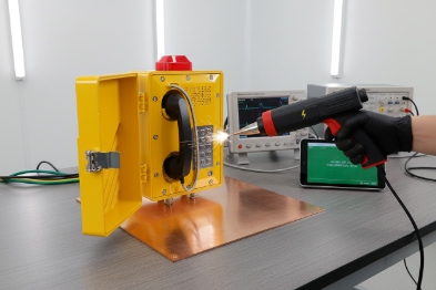
ESD immunity (EMC reliability): a person touches the keypad or handset and the device takes a high-voltage pulse. The phone must not reboot, drop registration, or mute audio.
Both can happen on the same unit. The controls overlap, but they are not the same.
What Ex rules push you to do for non-metallic external parts
Explosion protection standards for Ex equipment include requirements to avoid ignition risk from electrostatic charges 1 on external non-metallic materials. In practice, this drives common design choices:
-
limit the size and thickness of chargeable non-metallic surfaces
-
use materials or coatings that keep surface resistance under control
-
add conductive coatings with a defined bonding point when needed
-
add a specific condition of use (“X”) when the installation must provide the static control
This is why some Ex products have strict cleaning instructions, or warnings about dry cloth wiping. The product is still safe when used as instructed, but the site must respect those conditions.
A simple control map that helps during specification
| Static problem | Typical trigger | What “pass” looks like | Main controls |
|---|---|---|---|
| Electrostatic ignition (Ex) | Dry wiping, dust flow, wind, low humidity | No dangerous charge build-up on exposed parts | Material selection, surface resistance control, conductive bonding, surface limits, cleaning rules |
| ESD reboot or lockup (EMC) | Operator touch, glove removal, cable plug-in | No reboot, no lost SIP registration, audio stays stable | ESD protection circuits, filtering, shielding, isolation, proper earthing, surge/ESD arresters |
| “Hidden” static via cable | Long outdoor Ethernet runs, nearby lightning | No damage, auto-recover, ports survive | PoE surge/ESD combo protection, bonding, shield strategy, cabinet SPD plan |
A practical one-line requirement many buyers use
For harsh industrial sites, the cleanest anti-static requirement reads like this:
- “Ex telephone shall meet Ex electrostatic requirements for external non-metallic parts, and shall meet IEC ESD immunity with no loss of function. Vendor shall provide test levels, pass criteria, and installation grounding instructions.”
That one line stops most arguments later, because it forces the vendor to show both the Ex design intent and the EMC behavior.
If the next sections feel detailed, that is because anti-static failures are rarely dramatic. They look like random resets and water ingress after service. Both are preventable when the spec is clear.
Now it is time to lock in the ESD standards first, because that is the fastest way to prevent annoying “ghost failures” after commissioning.
Which ESD standards should be met—IEC 61000-4-2 contact/air levels and EN 55035 immunity for industrial sites?
An Ex phone can be perfectly safe and still be unusable if it reboots when a worker touches it in winter.
For ESD immunity, IEC 61000-4-2 is the core test method. Industrial sites often target Level 4 style severity (commonly ±8 kV contact and ±15 kV air) through an industrial immunity framework like IEC 61000-6-2. If the product is treated as multimedia equipment under CE EMC practice, EN 55035 is common and often uses lower ESD levels (commonly ±4 kV contact and ±8 kV air) unless the buyer specifies tougher levels.
How to pick between “industrial” and “multimedia” immunity paths
In real tenders, two patterns appear:
-
Industrial equipment approach: the buyer wants the phone to survive harsh plant disturbances. This often points to an industrial immunity standard set, where ESD is tested at higher levels and where surge and EFT 2 are also taken seriously.
-
Multimedia equipment approach: the buyer builds CE files around the common EN 55032 + EN 55035 pairing. This is often fine for many installations, but it may not match a loading rack reality unless the project adds tougher immunity targets.
The practical move is simple. If the phone is installed in a hazardous outdoor area with long cables and operators wearing PPE, the project should specify the higher behavior expectation, even if the base CE path is “multimedia.”
Ask for performance criteria, not only kV numbers
ESD tests can be “passed” while the product still becomes annoying on site. The key is the pass criteria:
-
The phone should not lose SIP registration.
-
The phone should not reboot.
-
The phone should not require manual intervention.
-
Audio should recover fast if a brief click occurs.
For emergency use, the best target is “no loss of function.” A temporary audio artifact can be acceptable if the call remains stable and the unit recovers by itself.
A buyer table that makes vendor reports comparable
| Item to specify | What to write | What to request as evidence |
|---|---|---|
| ESD method | IEC 61000-4-2 3 | Lab report with discharge points listed |
| Contact / air levels | Project-defined (example: ±8 kV contact, ±15 kV air) | Test levels, polarity, number of discharges |
| Discharge points | Keypad, handset, metal housing, RJ45 shield, earth stud | Photo of test setup and coupling planes |
| Pass criteria | No reboot, no lost registration, auto-recover | Event log showing uptime during test |
A practical “industrial site” recommendation
In my own project reviews, the safest path is to treat plant and terminal deployments as industrial, even when the phone looks like IT equipment. That keeps ESD, surge, and EFT expectations realistic. When a vendor can show stable behavior at tougher ESD levels, the same unit usually has fewer hidden field issues.
Next, EMC immunity alone is not enough. A device still needs a clear bonding and grounding approach, because poor grounding can turn a safe phone into a static generator.
How should enclosures be grounded—equipotential bonding, earth studs, and 316L conductive paths across hinges and cable glands?
A metal enclosure can look grounded and still float electrically. Then static charge and surge energy search for random paths through the electronics.
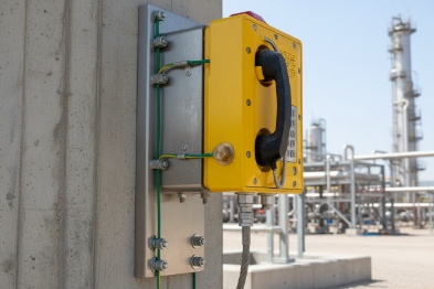
Explosion-proof telephones should be bonded into the site equipotential bonding network using a dedicated earth stud, short low-impedance conductors, and verified continuity across hinges, covers, and glands. For 316L stainless housings, the design should ensure a reliable conductive path across moving joints and cable entries, not only through paint or loose screws.
Equipotential bonding is the main goal, not “a wire to somewhere”
Grounding for an Ex telephone is not only about safety earth. It is about keeping the phone at the same potential as nearby metalwork so charge cannot build and discharge unexpectedly.
A strong grounding approach usually includes:
-
A clear external earth stud on the enclosure.
-
A short, thick bonding conductor to the nearest bonding bar or structure.
-
A defined torque and washer stack that cuts through oxidation and keeps contact stable.
Stainless steel details matter in coastal and washdown areas
316L 4 resists corrosion well, but it can still form surface films. Hinges and cover joints can also lose continuity if:
-
a gasket isolates two metal parts
-
paint or powder coating sits under the bonding surface
-
screws loosen over time from vibration
That is why good designs add:
-
bonding straps across hinged covers
-
serrated washers or bonding rings at earth points
-
a dedicated bonding path that does not depend on “contact by chance”
Cable glands and conduit entries must not break the bonding story
Cable entries are common failure points. A gland can seal well but isolate electrically. For anti-static control and surge control, the project should decide:
-
whether the cable shield is bonded at the phone end, cabinet end, or both
-
whether the gland provides shield termination
-
how the shield is managed in Zone 1/2 rules and in site earthing rules
For many outdoor PoE runs, shield management must be consistent end-to-end. Random shield bonding causes noise loops and can make ESD behavior worse.
A grounding checklist that field teams can follow
| Grounding point | What “good” looks like | What “bad” looks like |
|---|---|---|
| Earth stud | Metal-to-metal contact, correct washers, torque marked | Stud covered by paint, loose nut, no washer |
| Hinge / cover | Bond strap or proven continuity | Floating door, continuity only when pressed |
| Cable gland | Shield termination method documented | Shield cut back and left floating |
| Bonding conductor | Short, thick, protected from corrosion | Long thin wire, routed with signal cables |
A simple commissioning test that prevents later blame
A quick continuity test across the enclosure, cover, and earth stud should be part of commissioning. It is cheap, fast, and it catches assembly problems before the site blames the network or the SIP server.
Next, even perfect grounding does not stop every ESD event. The phone still needs circuit-level protection so a static hit does not travel into the PHY, CPU, or audio path.
What circuit protections limit ESD—TVS diodes, RC snubbers, isolation transformers, and shielded PoE with surge/ESD combined arresters?
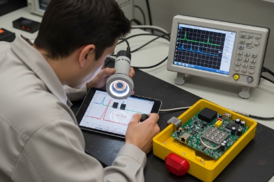
Many field ESD failures do not look like a “zap.” They look like random packet loss, one dead Ethernet port, or one keypad that starts misbehaving.
Circuit protection should clamp ESD fast and keep energy away from sensitive silicon. Typical measures include TVS diodes on external lines, RC networks on switch contacts, Ethernet magnetics for isolation, common-mode filtering, and coordinated surge/ESD protection for PoE lines. Shielded Ethernet can help, but only with a clear bonding plan and proper combined protectors at the right locations.
Think in layers: entry clamp, isolation, then filtering
A clean circuit protection design uses layers that work together:
-
Clamp at the port: TVS diodes 5 near the connector take the first hit.
-
Isolate where possible: Ethernet magnetics provide galvanic isolation between cable and silicon.
-
Filter remaining noise: common-mode chokes 6 and RC networks reduce ringing and false triggers.
This layered approach matters because ESD is fast. If the clamp is far away on the PCB, the energy travels through traces first. That is where damage happens.
Protect the paths that operators touch
For telephones, the touch points are predictable:
-
keypad matrix lines
-
hook switch inputs
-
handset audio lines
-
metal housing and earth connection
-
Ethernet RJ45 area and any external I/O
The protection plan should cover the full path from “finger touch” to “sensitive IC.”
PoE needs coordinated protection, not random parts
PoE ports are common ESD entry points, and they also face surge risks from long outdoor runs. The product-level protection helps, but the system design matters too:
-
A PoE switch cabinet should use proper SPD protection on incoming lines where needed.
-
Outdoor runs often benefit from a mid-span or cabinet-level surge protector.
-
If shielded cable is used, shield bonding must be consistent to avoid noise loops.
A practical protection table used in design reviews
| Line / port | Typical protection elements | What failure it prevents |
|---|---|---|
| RJ45 / PoE | Ethernet magnetics + TVS + common-mode choke | Dead PHY, random reboots, link drops |
| Keypad inputs | TVS + series resistors + debounce logic | Ghost presses and MCU latch-up |
| Hook switch | RC filter + TVS | False on/off-hook and resets |
| Audio lines | TVS + filtering + ESD-safe codec layout | Loud pops and damaged audio IC |
| Alarm I/O | TVS + series resistor + isolation option | Field wiring ESD damage |
A common mistake: over-trusting “shielded cable”
Shielded Ethernet does not automatically solve ESD. It moves energy to the shield, which is good only if the shield has a safe path to earth. If the shield is left floating or bonded inconsistently, it can create new problems. The best results come when:
-
the phone design supports shield termination cleanly
-
the installation standard defines where shields are bonded
-
the cabinet includes surge/ESD coordination 7 for long runs
Next, even the best product design fails when installation habits are weak. Static control is partly a human process. That process must be written into commissioning and maintenance.
Which installation practices prevent static—anti-static gloves, ESD bags, humidity control, and grounding tests during commissioning and maintenance?
A phone that passes every lab test can still fail after one dry wipe with the wrong cloth or one maintenance job that forgets a bonding strap.
Static prevention in the field is built on handling discipline (ESD bags and grounded work surfaces), controlled cleaning and PPE practices, humidity awareness, and simple grounding and continuity tests during commissioning and maintenance. The goal is to keep Ex electrostatic conditions intact and keep EMC behavior stable over time.

Handling and storage: stop ESD damage before the phone is even installed
A surprising number of ESD failures happen during warehouse handling and bench setup. Good practice includes:
-
store electronics in ESD-safe bags
-
use grounded benches when configuring SIP parameters
-
avoid placing the unit on insulating foam or plastic sheets
-
keep protective caps on ports until final wiring
These steps are basic, but they reduce hidden damage that appears months later as “random faults.”
PPE and cleaning: control the things that create charge
In hazardous areas, cleaning and maintenance are part of “normal conditions of use.” That matters because electrostatic risk often comes from dry wiping on non-metallic surfaces.
Good site practice often includes:
-
avoid aggressive dry rubbing on plastics and label films
-
use cleaning methods allowed by the product documentation
-
use anti-static gloves 8 when handling exposed polymer parts in dry climates
-
do not “upgrade” gaskets, label films, or keypad covers without approval
This is also where humidity matters. Low humidity increases static build-up. A site cannot change weather, but it can control indoor maintenance rooms and it can plan how and when deep cleaning is done.
Commissioning checks that should be routine
A commissioning checklist should include:
-
verify bonding conductor is installed and tightened
-
continuity check between earth stud and cover/hinge
-
verify cable gland torque 9 and correct sealing washers
-
verify shield termination method matches the network design
-
perform a functional call test after final tightening
These checks also protect IP rating and Ex integrity, because loose glands are both a water ingress risk and an electrical bonding risk.
Maintenance schedule: small checks prevent big failures
In harsh sites, a light inspection schedule keeps static control stable:
-
check bonding straps and earth connections for corrosion
-
re-torque critical fasteners if the site standard allows it
-
check glands for looseness and cable sheath damage
-
confirm labels remain legible without risky cleaning methods
A field practice table that works well
| Stage | What to do | What it prevents |
|---|---|---|
| Storage | ESD bags and protected ports | Latent ESD damage |
| Installation | Equipotential bonding 10 verified | Floating enclosure and random discharge paths |
| Commissioning | Continuity test across cover and earth | “Looks grounded” but is not grounded |
| Operation | Cleaning rules respected | Electrostatic ignition risk and cosmetic damage |
| Maintenance | Inspect straps, glands, and seals | IP loss and rising ESD sensitivity |
When these practices become routine, the phone behaves the same in year three as it did on day one. That is the real goal of anti-static control.
Conclusion
Anti-static control for Ex telephones needs Ex-safe materials, solid bonding, strong ESD protection circuits, and disciplined installation and maintenance that keep grounding and seals correct.
Footnotes
-
[Basic principles of electrostatic discharge and how static electricity is generated and controlled.] ↩
-
[Electrical Fast Transient testing simulates rapid voltage bursts to verify device immunity.] ↩
-
[International standard specifying testing methods for immunity to electrostatic discharge.] ↩
-
[Low-carbon austenitic stainless steel commonly used for its corrosion resistance in harsh environments.] ↩
-
[Transient Voltage Suppression diodes used to protect circuits from voltage spikes.] ↩
-
[Inductive components used to block high-frequency noise common to two or more lines.] ↩
-
[Standards for devices protecting electrical equipment from transient overvoltages.] ↩
-
[Gloves designed to prevent static buildup and discharge during sensitive component handling.] ↩
-
[Guidelines ensuring proper installation and sealing of cable glands to maintain safety ratings.] ↩
-
[Electrical connection maintaining conductive parts at the same potential to prevent shocks.] ↩


