Many ATEX phone projects fail at the “small” details. A wrong ring voltage, weak surge plan, or poor grounding can cause no-ring faults and audit pain.
An Ex telephone must match the FXS electrical profile (loop current, REN, ring voltage/cadence), and the installation must preserve Ex/IP integrity with correct bonding, surge protection, isolation strategy, and documented FAT results.

FXS integration essentials that keep Ex phones stable and audit-safe
Understand what FXS is, and where it belongs in an Ex project
FXS 1 is the analog “station” port that provides talk battery, dial tone, loop current, and ringing. In real sites, FXS can come from an IP PBX with FXS cards, an analog gateway (ATA), or a legacy PBX shelf. The explosion-proof telephone is the analog endpoint. So the phone must behave like a standard analog device, while the installation must still respect hazardous-area rules.
The easiest way to reduce risk is to keep the FXS source equipment in a safe area or a certified enclosure outside the Zone. Then only the two-wire analog pair enters the hazardous area. This avoids putting complex electronics inside the Zone. It also makes maintenance simpler.
Treat FXS as an electrical interface with tolerances, not a single “spec”
In practice, FXS ports vary. The safe approach is to confirm that the phone supports typical ranges:
-
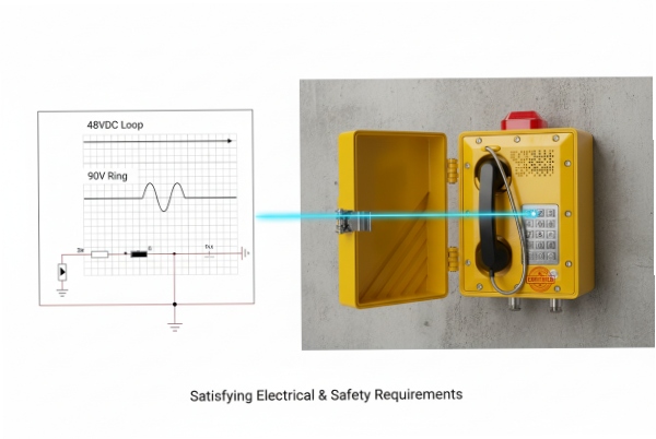
Talk battery (on-hook DC) around 48 VDC (varies by system)
-
Loop current in the 20–60 mA range
-
Ring voltage often 70–90 Vrms (sometimes higher), commonly 20–25 Hz
-
Ring cadence depends on country and PBX profile
If the phone is high-power (loud ringer, beacon relay, heavy-duty keypad), it may draw more loop current or need a stronger ring source. This is why REN 2 and loop current must be treated together.
Use a simple pre-order compatibility sheet
A short compatibility sheet prevents the most common surprises:
| Item | What to record | Why it matters |
|---|---|---|
| FXS source type | PBX card, ATA, gateway, PABX | Impacts ring strength and DTMF 3 behavior |
| Region profile | ring cadence + tones + impedance | Avoids “works in lab, fails onsite” |
| Phone load | REN, ringer mode, accessories | Prevents weak ring/no ring |
| Hazard strategy | safe-area gateway vs Zone cabinet | Drives glands, bonding, inspection scope |
| Ta + IP | ambient range and ingress plan | Stops heat and leak failures |
Most integration issues are not “Ex problems.” They are analog interface mismatches. Once the basics are aligned, the Ex compliance work becomes much easier.
If the goal is a smooth commissioning, the next step is to lock the electrical targets first, then lock the hazardous-area installation method.
Many teams jump straight into wiring. That is where mistakes start. The best flow is: confirm loop current + REN + ring, then confirm earthing + surge plan, then pick the gateway/PBX, and only then write the FAT plan.
What loop current, REN, and ring voltage must the phone support?
Too many projects assume “any analog phone works on FXS.” Then the phone never rings, or it rings once and stops under real cable length.
An Ex telephone should support typical FXS talk battery and loop currents, have a conservative REN (lower is better), and accept the site’s ring voltage, frequency, and cadence profile used by the PBX or gateway.
Start with “ringing is the hardest part”
Dial tone usually works even on weak ports. Ringing is where the system fails first. Long cable runs add capacitance. Corrosion adds resistance. Dust-tight glands can add strain. So the ringer load matters.
Most industrial projects aim for:
-
Loop current capability: roughly 20–60 mA operating window
-
REN target: as low as practical (often ≤1 REN is a safe target for gateways)
-
Ring voltage acceptance: commonly 70–90 Vrms at 20–25 Hz
-
Cadence: match local tone plan (for example 2s on / 4s off, but it varies)
Do not treat these as universal constants. Treat them as “typical ranges” and confirm the exact FXS port specs.
Match REN to the worst-case topology
REN is a load concept that describes how hard the device is to ring. Gateways and PBX cards have a maximum REN they can ring per port. That maximum drops when:
-
cable lengths are long
-
ring frequency is non-default
-
multiple devices share one port (not recommended for emergency phones)
A safe design rule is one phone per FXS port, and keep REN margin. If the phone includes a very loud electromechanical ringer, REN can be higher. If it uses an electronic ringer, REN is often lower.
Use a compatibility table before FAT
| Parameter | Typical target range | What to check in the PBX/gateway |
|---|---|---|
| On-hook DC (talk battery) | ~40–60 VDC | output voltage and polarity behavior |
| Loop current | ~20–60 mA | current limit and line feed mode |
| Ring voltage | ~50–100 Vrms | max Vrms under load |
| Ring frequency | ~16–25 Hz (common) | selectable frequency profiles |
| REN capacity | port-dependent | maximum REN per port at chosen frequency |
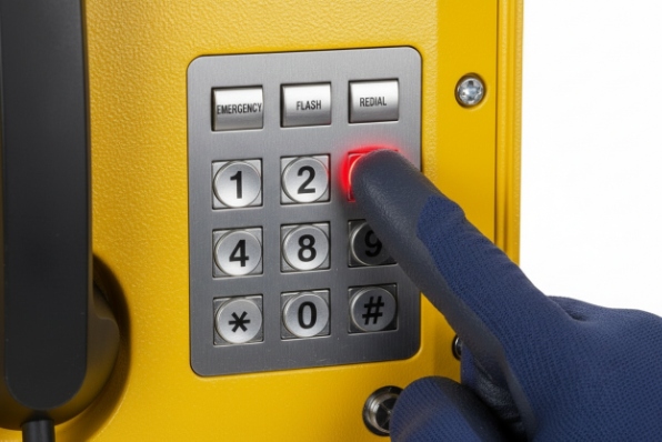
Small details that matter for emergency call points
For hazardous-area phones used as emergency points, also confirm:
-
Hook-flash support (if used for PBX features)
-
Caller ID (FSK/DTMF) if required
-
Line reversal and supervision behavior if used for alarms
-
DTMF reliability with the chosen codec chain (gateway detection settings)
Once the electrical targets are locked, the project moves to the installation controls that keep Ex t/IP integrity and avoid lightning damage.
How do I earth, surge-protect, and isolate FXS lines in ATEX areas?
One nearby lightning event can take down a whole row of phones. In hazardous areas, a surge event can also create unsafe faults if bonding is sloppy.
Bond the phone enclosure per the certified installation method, add surge protection at the correct boundary, use certified glands and shielding practices to keep IP/Ex integrity, and apply isolation or barriers only when required by the protection concept and site rules.
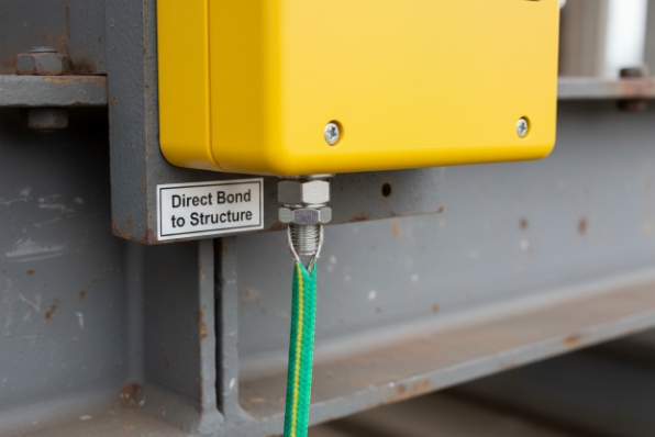
Grounding and bonding: keep it simple and consistent
For most heavy-duty Ex telephones, the enclosure has an external earth stud. That stud should bond to the site equipotential bonding 4 network using the conductor size and method required by the installation standard and the manual. The goal is to avoid floating metal that can hold charge and to provide a safe fault path.
Avoid “creative grounding” with multiple long earth routes. A single clear bonding path is easier to inspect and easier to maintain. If shielded cable is used, bond the shield in the way the site standard requires. Many plants prefer bonding shields at one end to reduce noise loops, but the final decision must follow the site EMC and safety rules.
Surge protection placement: protect the line where it enters the building or zone boundary
Surge protectors are most effective when installed at a defined boundary:
-
building entry point
-
marshalling cabinet in safe area
-
a certified junction box at the Zone boundary (if allowed and designed for it)
Use telecom-rated surge devices suitable for the voltage and line type. If surge devices are placed inside a hazardous area, they must be suitable for that area and installed in a compliant enclosure. Many projects avoid that by keeping surge protection in the safe area.
Cable glands and isolation: protect IP first, then protect the interface
Ex t 5 depends on enclosure protection by sealing. So the gland selection matters as much as the surge protector:
-
match thread type (metric vs NPT)
-
use the approved gland type and sealing washer/O-ring method
-
maintain the required IP level after installation
-
close unused entries with certified plugs
Isolation can mean different things. Sometimes it is galvanic isolation for noise and surge resilience. Sometimes it is intrinsic safety 6 barriers. Do not add barriers unless the protection concept requires it. A barrier can also change loop current and ring behavior, so it must be validated.
A practical install checklist for FXS lines into a dusty ATEX site
| Topic | What “good” looks like | Common failure |
|---|---|---|
| Bonding | short, direct bond to equipotential network | floating enclosure or loose bond lug |
| Surge | protection at boundary cabinet | no protection or wrong rating device |
| Glands | certified glands, correct thread, correct seal | thread adapters that loosen over time |
| IP integrity | gasket clean, covers torqued, unused entries plugged | dust ingress at cable entry |
| Documentation | wiring drawing + gland PN list | “field choice” hardware substitutions |
With earthing and surge planned, the next decision is the hybrid network architecture. That is where teams decide whether an FXS-to-SIP gateway or a PBX is the best integration path.
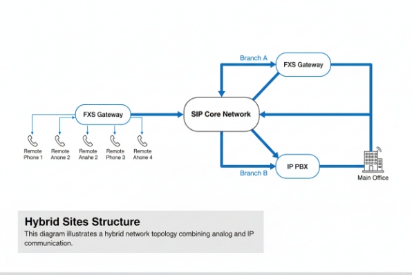
Do I need an FXS-to-SIP gateway or PBX for hybrid sites?
Hybrid sites often have SIP in the control rooms and analog in remote areas. If the wrong integration path is chosen, support becomes painful.
Most hybrid sites use an FXS gateway or an IP PBX with FXS ports in a safe area, then run analog pairs to Ex telephones. The right choice depends on scale, redundancy, and how central call routing must be managed.
Use an FXS gateway when you need simple bridging
An FXS-to-SIP gateway (or ATA) is a clean solution when:
-
the core system is SIP
-
only a limited number of analog Ex phones are needed
-
the phones are spread across long distances
-
you want fast deployment and easy replacement
In this model, each Ex phone gets a dedicated FXS port. The gateway registers to the SIP platform as endpoints. Call routing is done in the SIP core.
Use an IP PBX with FXS cards when you need central control
A PBX with FXS modules makes sense when:
-
many analog stations are needed
-
ring profiles, tones, and features need tight control
-
you need integrated paging, hunt groups, or emergency routing logic
-
redundancy and maintenance processes are already PBX-based
This also improves consistency in dialing plans and reporting, especially on large refinery sites.
Redundancy and power considerations
For emergency call points, design for failures:
-
redundant gateways or redundant PBX shelves for critical areas
-
dual power feeds where possible
-
clear labeling and port mapping for fast replacement
-
spare ports and spare cards
FXS ports also need stable power to ring correctly. A gateway on a weak UPS 7 can create intermittent “no ring” faults under load. This looks like a phone issue, but it is a power issue.
Architecture decision table
| Project size | Recommended path | Why it fits |
|---|---|---|
| 1–8 phones | FXS gateway/ATA | simplest, low overhead |
| 8–48 phones | multi-port gateway | easier scaling and management |
| 48+ phones | PBX with FXS cards or distributed gateways | central control or regional resilience |
| High-criticality | redundant gateways + SIP core resilience | avoids single points of failure |
After the architecture is chosen, the project needs a FAT 8 plan that proves the interface works before shipment. That is where dialing, DTMF, and ring cadence must be tested in a repeatable way.
How should I test dialing, DTMF, and ring cadence in FAT?
Many “FATs” only test audio. Then the client finds a cadence mismatch or DTMF mis-detection during SAT, and the project stalls.
A good FAT validates hook states, dialing, DTMF detection, ring cadence, and supervision under worst-case settings, using the exact gateway/PBX profile planned for the site.
Build a simple FAT sequence that mirrors real use
A repeatable FAT plan usually follows this flow:
1) Visual inspection of labeling, Ta, IP, and entry configuration
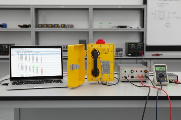
2) Electrical checks: on-hook voltage, off-hook loop current
3) Dial tone acquisition and dialing behavior
4) DTMF transmission and detection accuracy
5) Ringing: voltage, frequency, cadence, and ring trip
6) Speech: two-way audio level, noise, sidetone, echo perception
7) Abnormal checks: long cable simulation, low ring margin, high ambient simulation if possible
“Ring trip” is important. The system must stop ringing when the handset goes off-hook. Weak ring sources or timing issues can cause stuck ringing.
DTMF testing: test both generation and detection
For analog phones on FXS, DTMF is generated in-band. The gateway or PBX must detect it correctly. FAT should include:
-
fast and slow digit entry
-
long digit sequences
-
keypad bounce behavior if applicable
-
DTMF level settings on the gateway if configurable
If the gateway converts DTMF into SIP events, confirm the conversion is consistent. The main goal is that the remote side receives the right digits every time.
Ring cadence and tone profiles: test the site profile, not the default profile
Different regions use different cadences and tone plans. FAT should set the correct country profile on the gateway/PBX, then verify:
-
cadence timing matches the client requirement
-
ring frequency matches what the phone ringer expects
-
call progress tones are acceptable for users
A FAT acceptance table that clients understand
| Test case | Method | Pass criteria |
|---|---|---|
| On-hook voltage | meter at phone terminals | within FXS spec range |
| Off-hook loop current | meter in series | stable within phone operating range |
| Dialing | call known extension | call completes, no false hooks |
| DTMF | dial IVR or test receiver | 100% digit recognition |
| Ringing | verify cadence + ring trip | rings reliably and stops on answer |
| Long line margin | add line simulator or long cable | still rings and dials reliably |
| Documentation | record settings and results | repeatable test report |
A strong FAT report includes the gateway/PBX settings page captures, the measured values, and the exact phone configuration. This turns commissioning into a simple confirmation instead of a troubleshooting session.
Conclusion
Match FXS electrical limits first, then lock bonding, surge, glands, and the gateway/PBX profile, and prove everything with a structured FAT that measures ring, DTMF, and supervision.
Footnotes
-
Interface providing analog line service to subscriber equipment like telephones. ↩
-
Measure of the load a ringer places on a telephone line. ↩
-
Telecommunication signaling using two simultaneous tones for dialing and control. ↩
-
Practice of connecting metal parts to ground to prevent dangerous potential differences. ↩
-
Protection method where the enclosure prevents dust ingress and limits surface temperature. ↩
-
Protection technique limiting electrical and thermal energy to safe levels. ↩
-
Uninterruptible Power Supply providing emergency power when the input source fails. ↩
-
Factory Acceptance Test conducted to verify equipment meets requirements before shipment. ↩


