
One bad EMI burst can drop an emergency call in a hazardous area. The phone still looks “fine.” The risk hides inside emissions, immunity, and cabling mistakes.
An explosion-proof telephone must meet the EMC rules of the target market and the site environment. Pick the right emissions + immunity standards, test the real port setup, and back it with clear compliance documents and solid installation practices.

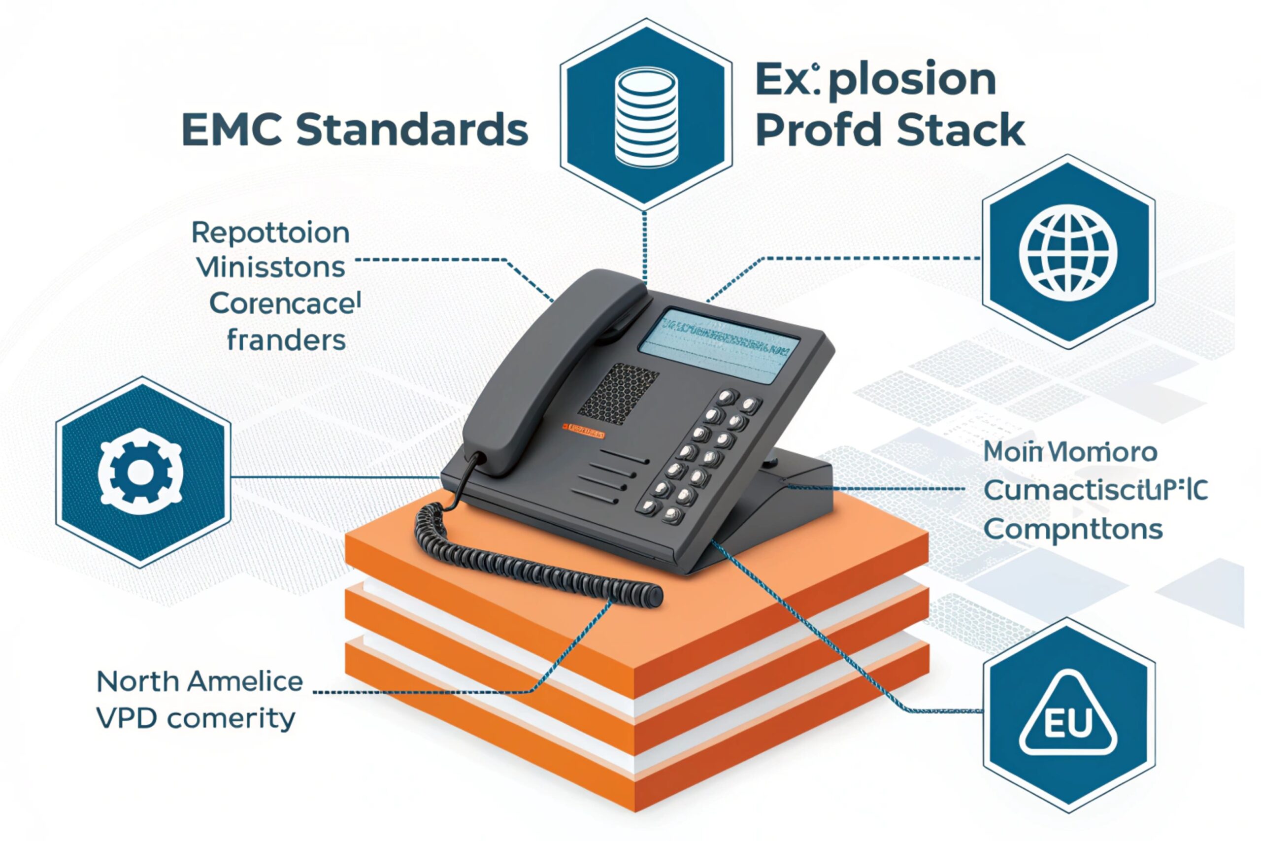
How to map EMC to an explosion-proof telephone?
Explosion-proof certification and EMC compliance solve different problems. “Explosion-proof” (ATEX/IECEx concepts) is about not igniting gas or dust. EMC is about not disturbing other equipment and not being disturbed. In real projects, both matter because an Ex telephone is often installed where motors, VFDs, switchgear, radios, and long outdoor cables all live in the same place.
A practical way to map EMC is to start from the ports and the real installation:
Start with the port list, not the brochure
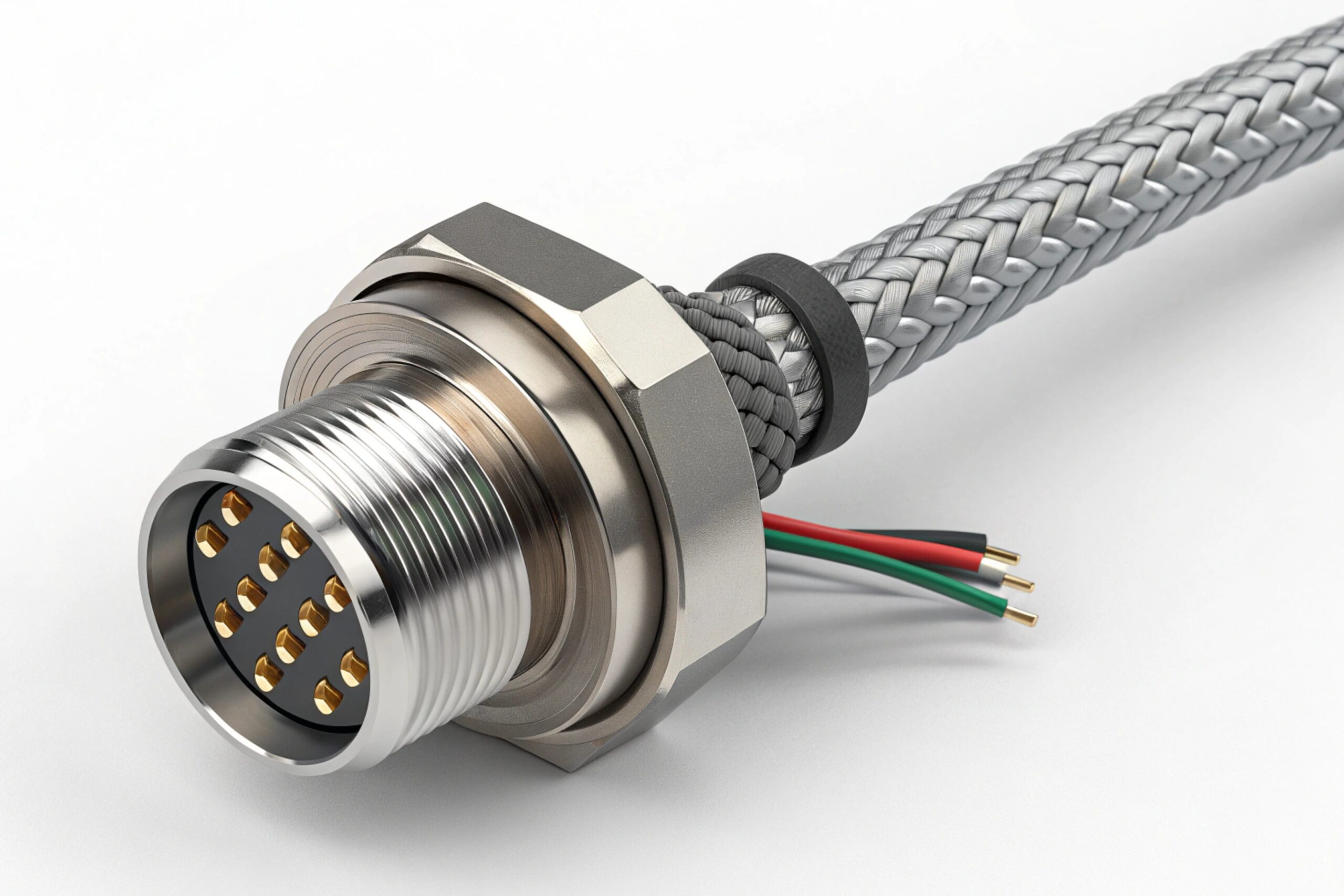
A hazardous-area SIP phone can have PoE Ethernet, DC input, AC input (via PSU), relay/alarm I/O, headset/handset lines, and sometimes RS-485 or other control ports. Every port is an antenna in some way. EMC tests are port-based. If the lab tests a “demo” setup and the site uses 80 meters of outdoor cable, the report still exists, but the risk stays.
Define “works normally” before testing
Immunity testing needs performance criteria. For a telephone, “works” should mean: stable registration, clear audio, keypad works, call can be placed and received, and it recovers after a disturbance. If the product resets and loses its SIP registration 1 after a surge, that is not a small issue in an emergency system.
Choose the standard set that matches the product family and the environment
Some phones fit a “multimedia / IT equipment” standard set. Some projects prefer “industrial generic” standards because the environment is harsh. In OEM work, we lock this decision early. It changes shielding, PCB layout, and the surge protection design.
| Port / interface on Ex telephone | Main EMC risk in the field | Typical test family to plan for | Design focus |
|---|---|---|---|
| Ethernet / PoE (copper) | Radiated RF pickup, conducted RF, surge from outdoor runs | 61000-4-3 / 4-6 / 4-5 style tests | Shield bonding, PoE magnetics protection, common-mode chokes |
| AC input (if used) | EFT from switching, surge, dips | 61000-4-4 / 4-5 / 4-11 | PSU filtering, MOV/TVS, hold-up, grounding |
| DC input | Surge, EFT, conducted RF | 61000-4-5 / 4-4 / 4-6 | TVS + filter, return path control |
| Signal / control I/O | EFT via long control cable | 61000-4-4, sometimes 4-5 | Clamp points, filtering, isolation |
| Metal enclosure & glands | Bonding gaps become EMI slots | Radiated emission / immunity | 360° shield termination, paint removal at bond points |
If this mapping step is done well, the rest becomes much simpler. If it is skipped, the project turns into “pass in the lab, fail on site.”
Now let’s go through the exact standards, immunity levels, documents, and installation practices in a way you can hand to a lab or an integrator.
Which standards apply—IEC/EN 55032 emissions, EN 55035 immunity, IEC 61000-6-2/6-4 industrial, FCC Part 15, and ICES-003?
Wrong standard selection is the fastest way to waste EMC budget. The lab can test perfectly and still deliver a report that does not fit your market claim.
For an explosion-proof telephone, the applicable EMC standards depend on (1) where it is sold (EU vs US/Canada), and (2) how it is classified (multimedia/IT style vs generic industrial).
EU: follow the EMC Directive, then pick harmonized standards
In the EU, the EMC Directive covers both emissions and immunity. A common route for SIP/IP telephones is the EN 55032 2 (emissions) + EN 55035 3 (immunity) pair when the product is treated as multimedia / IT style equipment. This pairing is widely used for equipment that has digital interfaces and behaves like modern communication endpoints.
If the site is clearly industrial and you do not have a strong product-family reason to stay with EN 55032/55035, many manufacturers use the generic industrial standards IEC/EN 61000-6-4 (emissions) and IEC/EN 61000-6-2 (immunity) as a clean “industrial environment” proof set. Generic standards are especially useful when no dedicated product standard matches the device.
The CISPR guide is often used as a reference to choose the right CISPR family standard when classification is not obvious.
US and Canada: emissions compliance is the core requirement
In the US, FCC Part 15 4 (for unintentional radiators) is the key emissions rule set. For Canada, ICES-003 is the parallel requirement for emissions from digital apparatus. Immunity is usually not legally mandatory under FCC/ICES for most products, but industrial customers often demand IEC immunity anyway because the real environment is noisy.
Also note: if the explosion-proof phone includes an intentional radio (Wi-Fi/LTE), the scope expands beyond Part 15 unintentional emissions. Many Ex projects avoid radios inside hazardous areas for system reasons, but some still use them in certain zones. That decision changes compliance planning.
| Market claim | Emissions standard “family” | Immunity standard “family” | Notes for Ex telephone projects |
|---|---|---|---|
| EU CE (industrial site) | EN IEC 61000-6-4 | EN IEC 61000-6-2 | Good fit for harsh plants, long cables, switchgear rooms |
| EU CE (multimedia/IT style) | EN 55032 | EN 55035 | Common for SIP endpoints, network devices, office + light industrial |
| USA | FCC Part 15 (unintentional radiator) | Often customer spec (IEC) | FCC focuses on emissions and test procedure rules |
| Canada | ICES-003 | Often customer spec (IEC) | ICES focuses on emissions limits and admin labeling/docs |
The shortest path to a clean compliance plan is this: decide the market claim first, then pick the smallest standard set that fully supports that claim, then test the real configuration.
What immunity levels are required—ESD 61000-4-2, EFT 4-4, surge 4-5, radiated/conducted RF 4-3/4-6, dips 4-11?
A phone can “pass” a light immunity plan and still crash on a real site. Industrial plants do not produce polite disturbances. They produce fast edges, big surges, and continuous RF noise.
If you use IEC/EN 61000-6-2 for an industrial explosion-proof telephone, it sets clear minimum immunity levels across enclosure, signal ports, DC ports, and AC ports.

Baseline industrial immunity levels (IEC/EN 61000-6-2 style)
For enclosure phenomena, the industrial baseline includes:
-
Power-frequency magnetic field: 30 A/m
-
Radiated RF: 10 V/m from 80–1000 MHz, and 3 V/m from 1.4–6.0 GHz
-
ESD: ±4 kV contact, ±8 kV air
For signal/control ports and DC/AC power ports, the baseline includes:
-
Conducted RF (common mode): 10 V (rms) from 0.15–80 MHz
-
EFT (fast transients): typically ±1 kV for signal/control and DC ports, and ±2 kV for AC power ports
-
Surge: signal/control line-to-earth ±1 kV; DC line-to-earth ±1 kV and line-to-line ±0.5 kV; AC line-to-earth ±2 kV and line-to-line ±1 kV
-
Voltage dips / interruptions on AC input: levels aligned with IEC 61000-4-11 5 (for example, a short 0% dip and longer reduced-voltage dips; plus long interruption cases)
The key point is not only the numbers. It is the port condition. Many tests apply only when cables can exceed a certain length, or when a port interfaces to long-distance lines. In hazardous-area projects, long cable runs are common. So those “only if long cable” notes often become “yes, required.”
When to go beyond baseline
Some customers ask for higher ESD (like ±8 kV contact and ±15 kV air) because users wear gloves, work in dry environments, and touch metal often. Some ask for ring-wave or other tests when the power network is dirty. These are not always mandatory under a chosen base standard, but they can be smart in refineries, mines, and outdoor petrochemical sites.
Here is a simple table you can use in a spec sheet or customer approval checklist:
| Immunity phenomenon | Typical port | Baseline industrial level (example set) | What “failure” looks like for a phone |
|---|---|---|---|
| ESD (61000-4-2) | Enclosure / keypad | ±4 kV contact, ±8 kV air | Reboot, stuck keypad, audio drop |
| EFT (61000-4-4) | AC or I/O cables | ±2 kV (AC), ±1 kV (I/O/DC) | Random key presses, SIP re-register loop |
| Surge (61000-4-5) | AC, DC, long lines | Up to ±2 kV L-E (AC), ±1 kV L-E (signal/DC) | Dead port, PoE negotiation fails |
| Radiated RF (61000-4-3) | Enclosure | 10 V/m (80–1000 MHz), 3 V/m (1.4–6 GHz) | One-way audio, echo, codec glitches |
| Conducted RF (61000-4-6) | Cables | 10 V (rms) | Touch-tone errors, control I/O false triggers |
| Dips/interruptions (61000-4-11) | AC input | Standard dip/interruption profile | Call drops, device never recovers |
In my experience, the biggest hidden risk is surge on outdoor Ethernet/PoE or long control cables. Many phones are “fine” in an office lab. Then a real cable run acts like a lightning sensor.
Do EMC documents include EU DoC, CB reports, lab ISO/IEC 17025 accreditation, and test summaries in datasheets?
Most delays in B2B projects do not come from failing tests. They come from missing paperwork or unclear scope. A distributor asks for one line. An integrator asks for a full technical pack. A project consultant asks for test levels and performance criteria.
A complete EMC document set should prove the market claim (EU/US/Canada), show the tested configuration, and show that the lab and methods are credible.

What is “must-have” for EU EMC compliance
For CE under the EMC Directive, an EU Declaration of Conformity (DoC) is required. It should list the manufacturer, product identification, the directive(s), and the applied standards. The EMC Directive also defines that the DoC follows a model structure and is kept with technical documentation for the retention period. For practical work, the DoC is the public-facing document, and the test report is the technical evidence behind it.
A good technical file typically includes:
-
EMC test report(s) for emissions and immunity
-
Test setup photos, cable list, and operating modes used during tests
-
A short risk assessment and design controls (filters, shielding, bonding points)
-
User instructions that match the tested configuration (grounding, cable types, SPD requirements)
Where CB reports fit (and where they do not)
CB reports are mainly about safety (for example, IEC 62368-1 or similar safety standards). They are not a replacement for EMC evidence. Still, many buyers request CB documents because they want a clean safety story for global projects. In an explosion-proof telephone 6, you may also have Ex certificates and Ex test reports. Those are separate from EMC, but customers often want them in the same “compliance folder.”
Why ISO/IEC 17025 matters in real procurement
ISO/IEC 17025 accreditation is not always legally required for EMC testing in every market. Still, it is a strong trust signal. It tells the buyer that the lab follows a recognized quality system and has an accredited scope for the test methods. In large tenders, this can be a pass/fail document request.
| Document | Who issues it | What it proves | What to check |
|---|---|---|---|
| EU DoC | Manufacturer | Legal CE claim basis | Correct directives and standards listed |
| EMC test report | Test lab | Measured emissions + immunity results | EUT configuration, cable lengths, pass criteria |
| Lab accreditation (ISO/IEC 17025) | Accreditation body / lab | Lab competence for test scope | Scope includes the relevant IEC/CISPR tests |
| CB report/certificate | Certification body | Electrical safety compliance | Standard edition, factory name, product model |
| Datasheet test summary | Manufacturer | Quick customer screening | Levels shown match the full report |
| Ex certificate set | Ex body | Hazardous area protection concept | Marking matches the zone and gas group |
The simplest rule: a datasheet summary helps sales, but the project team will still ask for the full report and the DoC.
What installation practices ensure EMC—shielded cabling, grounding, SPD coordination, ferrites, and segregation from high-power lines?
Many “EMC problems” are installation problems. The phone is blamed because it is visible. The real cause is often a cable route next to a VFD output, a floating shield, or an SPD installed in the wrong place.
The best EMC installation is simple: control cable routing, bond shields correctly, coordinate surge protection, and keep noisy power away from communication lines.
Shielded cabling done the right way
For Ethernet in industrial sites, use shielded twisted pair (STP) when the environment is noisy. Then terminate the shield correctly. A shield that is connected at one end only can behave like a long antenna at certain frequencies. A shield connected poorly through paint or loose glands also fails. For metal Ex enclosures, the cable gland and the enclosure bond must create a solid 360° connection. This is where many field installs get weak.
Grounding and bonding rules that prevent “mystery resets”
The goal is equipotential bonding 7. The enclosure, mounting plate, and local grounding bar should be bonded with low impedance. This does not mean random extra wires. It means short, wide bonding where possible, and no loose, long pigtails for shields.
SPD coordination: protect where energy enters, not where it explodes
For outdoor runs, SPDs should be placed at cable entry points and coordinated in stages. A common pattern is:
-
Primary protection at building entry (bigger energy handling)
-
Secondary protection near the device (faster clamping, lower let-through)
For PoE lines, use surge protectors rated for the network speed and PoE power. If the protector breaks the PoE handshake, the “protection” becomes downtime.
Ferrites and segregation: cheap fixes when used correctly
Ferrites can help when a cable is acting like an antenna. They are not a cure for a missing ground bond or bad routing. Use them near the enclosure entry, and only after confirming the dominant noise path.
Segregation is still one of the highest ROI actions:
-
Keep comms cables away from high-power AC and motor outputs
-
Cross power lines at 90° if crossing is unavoidable
-
Avoid parallel runs next to VFD outputs
Here is a field checklist that matches what we see in real industrial sites:
| Field symptom | Most likely installation cause | Fast check | Practical fix |
|---|---|---|---|
| Random reboot when motor starts | Surge/EFT coupling on power or DC line | Look for shared conduits with motor power | Add SPD, reroute, improve bonding, add filter |
| SIP drops during radio use | Poor shield termination, high RF field | Check shield continuity at gland | 360° shield bond, add ferrites, improve enclosure bonding |
| Keypad triggers by itself | EFT on long I/O cable | Check I/O cable route and length | Clamp/filter I/O, separate routing, add transient protection |
| PoE link flaps in storms | Surge on outdoor Ethernet | Inspect entry protection | Add coordinated Ethernet SPD, correct grounding |
| Noise in audio | Ground loops or poor bonding | Measure potential between points | Single bonding strategy, avoid long pigtails |
One personal lesson from a refinery project: the phone hardware was stable, but calls still dropped during pump starts. The fix was not firmware. It was rerouting one Ethernet run away from a VFD cabinet and bonding the shield correctly at the enclosure gland.
Conclusion
Explosion-proof telephones need the right EMC standard set, clear industrial immunity targets, a complete compliance document pack, and disciplined installation. That combination prevents surprises after deployment 8.
Footnotes
-
Protocol process where a SIP user agent identifies its location to a registrar server. [↩] ↩
-
European standard for electromagnetic compatibility of multimedia equipment – Emission requirements. [↩] ↩
-
European standard for electromagnetic compatibility of multimedia equipment – Immunity requirements. [↩] ↩
-
US Federal Communications Commission regulations governing electromagnetic interference from digital devices. [↩] ↩
-
Standard specifying voltage dips, short interruptions, and voltage variations immunity tests. [↩] ↩
-
Hazardous area telephone designed to operate safely in explosive gas or dust environments. [↩] ↩
-
Electrical connection putting various exposed conductive parts at substantially the same potential. [↩] ↩
-
Strategic approach ensuring electromagnetic compatibility through standards compliance and correct installation. [↩] ↩


