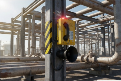
A single static zap can freeze a hazardous-area phone at the worst time. That small failure can block emergency calls and delay response.
For most industrial hazardous sites, IEC 61000-4-2 Level 4 is the right baseline: ±8 kV contact and ±15 kV air, with no resets, no configuration loss, and quick self-recovery of SIP, audio, and I/O.

ESD on Ex Telephones: Pick the Level, Then Prove Behavior?
Explosion-proof is not the same as ESD-robust
Explosion-proof certification controls ignition risk in gas or dust zones. ESD immunity controls uptime and functional safety in daily use. These are different problems. A phone can be fully certified for hazardous areas and still reboot when an operator touches the keypad after walking on an epoxy floor. The metal enclosure helps, but the discharge still finds a path. The path can be the keypad bezel, the hook switch, the handset cord, the shield of the RJ45, or an I/O terminal.
A good ESD requirement starts with the environment. Refineries, chemical plants, mines, and tank farms behave like industrial EMC locations. People wear PPE and gloves. Weather swings add static. Operators touch devices fast and with force. This makes contact discharge more important than air discharge for most Ex telephones. The next step is to define what “pass” means. A “pass” that allows a reset is not good enough for a safety phone. A “pass” that allows loss of SIP registration for several minutes is also not good enough.
It helps to treat ESD as a system test, not a component test. The ESD gun is a repeatable source. The phone is the target. The site grounding and cabling decide how the current returns. That is why the spec should include test points, performance criteria, and evidence like logs.
| Item to define | What to write in the spec | Why it matters in the field |
|---|---|---|
| Standard and level | IEC 61000-4-2 Level 4 | Avoids “marketing level” confusion |
| Discharge types | Contact + air + indirect to planes | Catches both touch and field upsets |
| Performance rule | No reset, no config loss, auto recovery | Protects emergency readiness |
| Test points | Keypad, hook, handset, enclosure, terminals | Matches real operator touch points |
The next sections break the requirement into simple choices that procurement teams and integrators can apply without guessing.
This is where many projects save time. A clear ESD spec reduces failures during FAT, and it reduces repeat site visits after commissioning.
Does IEC 61000-4-2 Level 4 mean ±8 kV contact and ±15 kV air for compliance?
Static numbers look easy, but the test only makes sense when the discharge method matches the phone surface and how people touch it.
Yes. IEC 61000-4-2 Level 4 is commonly stated as ±8 kV contact discharge and ±15 kV air discharge, and both polarities should be applied at defined points with repeat shots.
What Level 4 really means in a purchase document
Level 4 is a severity level for a standard test method. It does not guarantee “no issue ever.” It gives a repeatable stress that compares products. For an explosion-proof telephone, IEC 61000-4-2 Level 4 1 is a strong baseline because operators touch the device often, and the phone must stay ready for calls.
Level 4 includes two direct discharge methods:
-
contact discharge 2 up to ±8 kV where a metal tip can touch a conductive surface.
-
air discharge 3 up to ±15 kV where contact discharge is not possible, like some plastic surfaces or deep recesses.
On real Ex phones, contact discharge is usually the main threat because the enclosure is metal and the hook parts and screws are often conductive. Air discharge is still needed for plastics such as keypads, handset parts, label windows, and rubber seals where a contact tip cannot make a stable connection.
A practical compliance plan also includes indirect discharges, because ESD creates fields that can upset electronics even when the current does not go straight into a sensitive node. That is why the standard uses coupling planes 4, because ESD creates fields that can upset electronics even when the current does not go straight into a sensitive node.
Test plan details that avoid “easy passes”
A basic, fair test plan is consistent and repeatable.
| Test item | Typical setup | What to watch |
|---|---|---|
| Polarity | Positive and negative | Both can trigger different failures |
| Repetition | Multiple shots per point | One shot is not enough |
| Contact method | Use contact when possible | It is more repeatable than air |
| Air method | Use for plastics and gaps | Use stable approach speed |
In my experience, a strong vendor does not hide from Level 4. The vendor defines the points, runs both polarities, and shows that the phone stays stable with the same firmware and settings that ship to the site.
Which performance criteria should an explosion-proof telephone meet during ESD tests?
Many reports say “PASS” but never say what the phone did during the zap. That is where disputes start after deployment.
For an Ex telephone used for safety and operations, Criteria A behavior is the best target: no resets, no frozen UI, no config loss, and no stuck SIP state, with only minor and brief effects allowed.
Why Criteria A is the right goal for a safety endpoint
IEC 61000-4-2 allows the performance criteria to be defined by the relevant product standard or the agreement between buyer and supplier. For an explosion-proof telephone, the buyer usually cares about readiness more than cosmetic behavior. A short audio click can be acceptable. A reboot is not acceptable. A lost configuration is never acceptable.
A useful way to write Criteria A for a phone is to translate it into functions:
-
The phone does not reboot or hang.
-
The keypad, hook switch, and handset audio remain usable.
-
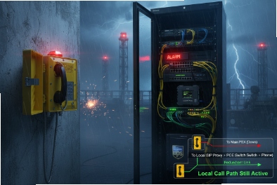
The device keeps SIP 5 registration or restores it quickly without manual action.
-
The device does not drop into a “half alive” state where the screen works but SIP fails.
-
Alarm outputs and inputs do not latch or false trigger beyond a defined, short window.
Some projects accept Criteria B for non-critical features, like a temporary screen glitch, as long as the device returns to normal by itself. Still, for emergency dialing and hotline keys, Criteria A is a safer and clearer request.
Add measurable recovery limits, not vague words
The test should include time limits, because “recovery” can mean one second or ten minutes.
| Function | Suggested requirement | Why it is practical |
|---|---|---|
| Reboot count | 0 during ESD | Reboots hide deeper design issues |
| Config retention | 100% retained | Field rework is expensive |
| SIP recovery | Auto, within defined seconds | Phone must stay ready |
| UI recovery | Immediate or within seconds | Operators do not wait |
Require evidence, not only a stamp
A strong supplier can provide:
-
system logs showing no watchdog events,
-
SIP logs showing no stuck registration loops,
-
test notes listing each point and voltage.
This is not about paperwork. It is about preventing a “pass” that still causes site downtime. When the criteria are clear, engineering teams can design the protection network and firmware behavior around a real target.
Where should ESD test points be applied on an explosion-proof telephone?
If the test points do not match how people touch the phone, the test becomes a lab exercise that misses field failures.
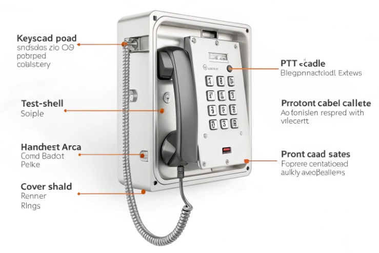
ESD points should cover every accessible touch surface and every external connection: keypad, function keys, hook switch, handset and cord, metal enclosure seams, mounting screws, cable gland area, and any exposed I/O terminals.
Direct discharge points: touch surfaces and edges
A user touches what is reachable. For explosion-proof telephones, that list is predictable:
-
Keypad and metal bezel or key frame
-
Emergency call button and its ring
-
Hook switch lever and cradle contact area
-
Handset body near the ear and mouth area
-
Handset cord strain relief and metal connector rings
-
Metal enclosure front plate, corners, seams, and exposed fasteners
-
Nameplate frames and protective grilles
Edges and seams matter because ESD likes sharp geometry. The current can jump into a gap, then travel along internal bonding paths. That is why testing only the “big flat metal” is not enough.
Indirect discharges: coupling planes to catch field upsets
Indirect discharge to a horizontal or vertical coupling plane is important for electronics inside a metal box. The phone may not be the direct target, but the field couples into cables and PCB loops. This test often exposes weak reset circuits, poor shielding around the codec, and weak bonding between the front plate and the rear housing.
Terminal and connector points: where ESD enters the electronics
Even if I/O terminals sit behind a cover, they can still be accessed during service. Ethernet shields and cable glands are also common entry points. If the phone supports external inputs for door sensors, beacons, or alarms, those terminals must be in the plan.
| Area | Example points | Common failure seen |
|---|---|---|
| User interface | Keypad, buttons, display window | UI freeze or false key events |
| Mechanical parts | Hook switch, cradle, screws | Reset due to ground bounce |
| Handset path | Handset shell, cord entry | Audio glitch or mic mute |
| External ports | RJ45 shield, DC input, I/O terminals | SIP drop or I/O latch |
A complete point list makes supplier comparisons fair. It also avoids a hidden gap where the phone “passes” but still fails when an operator touches the hook switch after a dry shift.
What design and installation measures make an Ex telephone robust against ESD?
Most ESD problems are solved with good current paths, good bonding, and the right protection parts at the right place. Some are solved with simple site practices.
Robustness comes from layered ESD protection at every port, tight chassis bonding, controlled shielding, and careful material choices for plastics, plus good installation like shield termination and equipotential grounding.
Device design: stop the current, then control the return path
Good ESD design is not only adding TVS diodes. It is about where the energy goes.
-
TVS protection 6 on exposed interfaces: use low-capacitance arrays for Ethernet pairs, and stronger TVS devices for DC and I/O.
-
Series impedance and filters: small resistors or ferrites slow the edge and reduce peak current into IC pins.
-
Common-mode chokes on Ethernet and long I/O: these reduce common-mode injection into the PHY and codec ground.
-
Solid chassis bonding: bond the front plate to the rear housing with low impedance. Use multiple bonding points, not one thin strap.
-
Protected reset and power rails: add RC filtering on reset, and add local decoupling near the MCU and audio codec.
-
Firmware resilience: avoid “stuck states” by using clean restart of SIP stack after link events, and log events for traceability.
Materials and gaskets: important for Ex phones with plastics
Some Ex telephone parts are non-metallic, like keypads, handset covers, and sealing gaskets. These can hold charge. Anti-static gaskets, conductive coatings, and controlled surface resistance plastics reduce charge build-up. The design must also keep the Ex rules in mind, so material choice and thickness follow the hazardous-area requirements.
Installation: the fastest win on site
Installation choices can decide if Level 4 feels easy or impossible.
| Measure | What to do | Why it helps |
|---|---|---|
| Shielded cabling | Use shielded twisted pair 7 where allowed | Reduces coupled fields |
| Shield termination | Use 360° bonding at gland, avoid long pigtails | Lowers high-frequency impedance |
| Equipotential bonding | Bond trays, cabinets, and device earth stud | Reduces touch voltage differences |
| Cable routing | Keep away from VFD outputs and motor feeders | Cuts noise sources near the phone |
| Port protection | Use coordinated SPDs for long runs | Reduces stress on internal TVS |
A phone that is strong in the lab can still fail in the field if the shield floats and the enclosure is not bonded. For hazardous sites, the bonding plan is part of safety. It also improves ESD behavior in a direct and measurable way.
Conclusion
Specify IEC 61000-4-2 Level 4, test real touch points, demand no resets and no config loss, and combine TVS and shielding with clean bonding and installation.
Footnotes
-
International standard defining the testing levels and methods for electrostatic discharge immunity. ↩ ↩
-
A direct ESD testing method where the electrode remains in contact with the device. ↩ ↩
-
Testing method where an ESD spark is discharged through the air to the equipment. ↩ ↩
-
Metal surfaces used in labs to simulate indirect ESD effects on nearby equipment. ↩ ↩
-
Signaling protocol used for initiating, maintaining, and terminating real-time sessions including voice calls. ↩ ↩
-
Electronic components designed to divert high-voltage transients away from sensitive integrated circuits. ↩ ↩
-
High-quality cabling with an electromagnetic shield to prevent interference in industrial communication. ↩ ↩