A door does not open, and everyone blames the reader. The reader beeps, the controller shows nothing, and the real issue is often the wiring or the bit format.
A Wiegand port is a simple reader-to-controller interface that sends credential bits over two data wires (D0/D1) plus ground. It is one-way, unencrypted, and still common because it is cheap and widely supported.

How does a Wiegand port actually send bits?
The electrical behavior in one picture
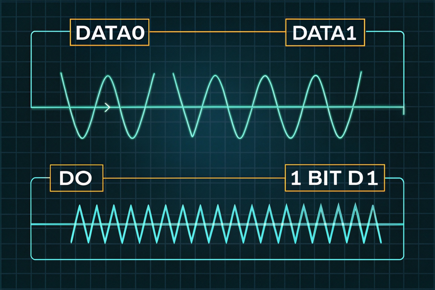
A Wiegand reader usually exposes DATA0 (D0), DATA1 (D1), and GND. Many readers also need power, often 12V, on separate wires. When idle, D0 and D1 sit high because the controller side provides pull-up resistors, often to about 5V. The reader output is often an open-collector output 1 (pulldown style). So the reader does not “drive high.” It only pulls a line low for a short pulse.
A binary 0 is a short low pulse on D0. A binary 1 is a short low pulse on D1. The reader sends a series of pulses, one bit at a time, with gaps between them. Pulse width is often around 100 µs and the gap is often around 1–2 ms, but devices vary. This is why mixing brands can work, yet timing edge cases still happen on long cables or noisy routes. If you want a clean reference diagram for decoding, see decoding the Wiegand protocol 2.
What the controller does with the bitstream
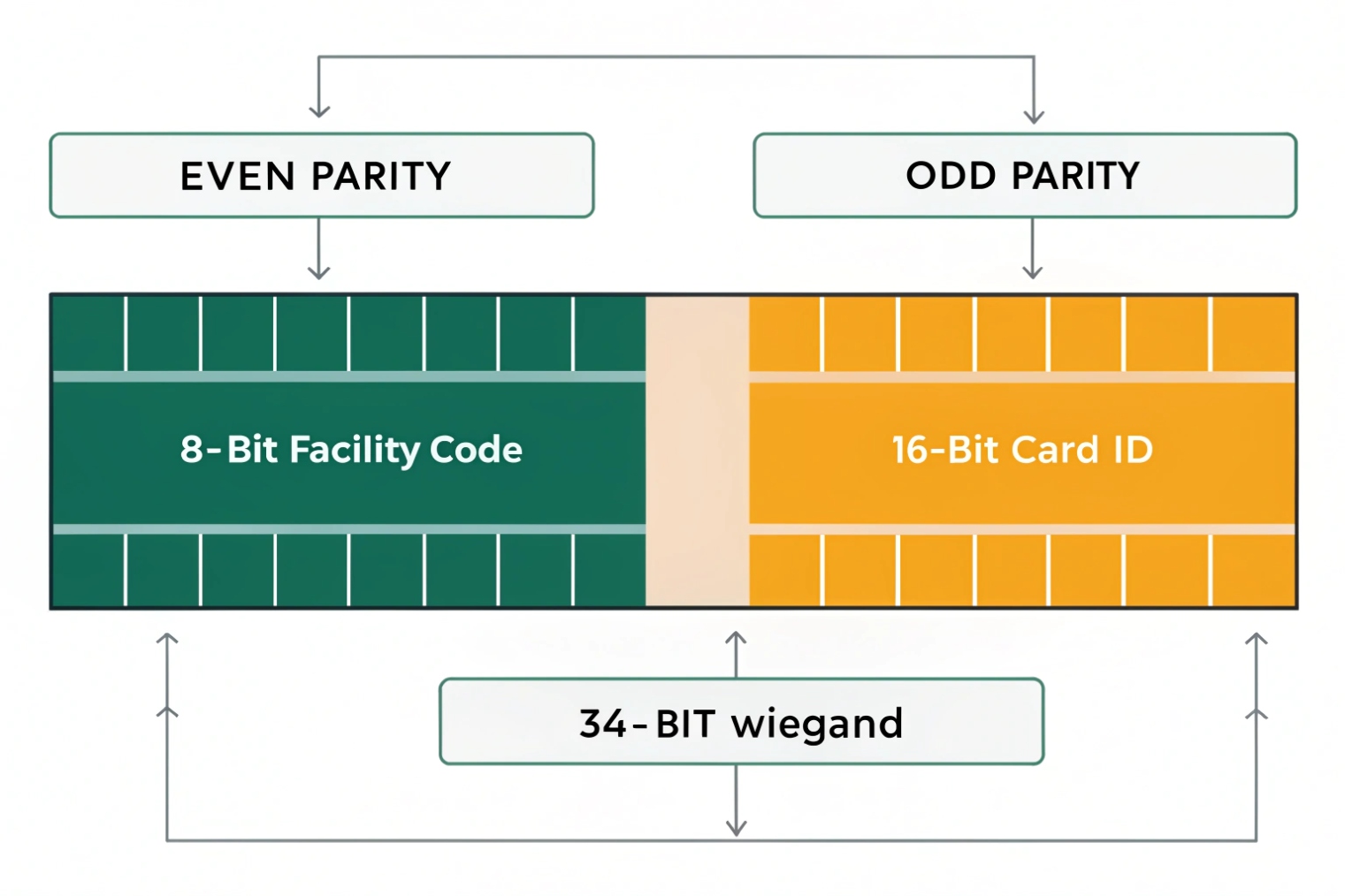
The controller counts bits and applies a format rule. In the classic 26-bit format, the first and last bits are parity. The middle bits carry a facility code and a card number. In 34-bit and other formats, the split changes, and the parity scheme can change too. If the controller expects 26-bit but the reader sends 34-bit, the controller may reject the credential or produce wrong numbers in logs.
The limits that matter in the field
Wiegand is simple, but it has no encryption, no device supervision, and no return channel. Anyone who can access the cable can sniff the bitstream and replay it. Long runs can also pick up noise. Many guides mention runs up to hundreds of feet, but real limits depend on cable, grounding, and environment.
| Wiegand trait | What it gives you | What it costs you |
|---|---|---|
| One-way reader → controller | Easy integration | No remote management, no supervision |
| D0/D1 pulse signaling | Works with simple hardware | Sensitive to noise and bad grounding |
| Many bit formats | Flexible for card systems | Format mismatch breaks access |
| Unencrypted data | Low cost and common | Vulnerable to sniffing and replay |
If the goal is fast installs and wide compatibility, Wiegand still fits. If the goal is modern security and monitoring, Wiegand should be treated as a legacy edge link and protected.
Next, the biggest question in every project is format support. Most “it does not read” tickets are format mismatch tickets.
Which Wiegand formats (26-bit, 34-bit) do my readers support?
Readers and controllers can both claim “Wiegand compatible,” yet still fail in real installs. Most of the time, the bits are fine. The format settings are not.
Most readers can output several Wiegand bit lengths, but the controller must be set to the same format. The common defaults are 26-bit and 34-bit, yet many systems also use 36/37/40+ bit formats tied to specific credential rules.
Start with the reader datasheet, not guesses
The fastest path is checking the reader manual for “output format.” Many readers can switch output via DIP switches, a configuration card, vendor software, or a keypad sequence. Some low-cost readers are fixed to 26-bit. Many modern multi-technology readers support multiple formats but ship with a default.
On the controller side, there is usually a setting like “Wiegand 26,” “Wiegand 34,” or “Custom.” Some controllers also let you map facility code and card ID fields. If the controller does not support custom parsing, it still can accept the raw bit length, then store the card number as a decimal or hex value. For examples of how systems define and parse custom Wiegand formats 3, it helps to review how parity and bit mapping are implemented.
What 26-bit and 34-bit mean in practice
26-bit is often used in classic HID-style systems. It typically has:
- 1 leading parity bit
- 8-bit facility code
- 16-bit card number
- 1 trailing parity bit
If you need an industry reference for the standard 26-bit layout (H10301), see HID’s overview in Understanding Card Data Formats 4.
34-bit is common in many enterprise deployments because it expands the ID space. The field split varies by vendor and card population rules. This is the part that creates confusion: “34-bit” is not always one universal split. It is a bit length, not a full identity standard.
A practical test method that saves time
In my projects, a simple approach works well:
1) Put a known good credential on the reader.
2) Confirm the controller logs show a stable number every swipe.
3) Compare that number to the printed card number or the access database number.
4) If the number changes, the format parse is wrong.
If the controller can show “raw bits” or “hex,” use that view. Raw views remove format assumptions and help match what the reader truly outputs.
| Format label | Typical use | Common risk |
|---|---|---|
| 26-bit | Legacy proximity systems | Too small ID space for large sites |
| 34-bit | Many corporate access systems | “34-bit” split differs by vendor |
| 36/37-bit | Some HID / custom populations | Controller may not support custom parsing |
| Custom Wiegand | Large deployments, migrations | Wrong parity or bit mapping causes rejects |
If the site needs stronger security, format choice does not fix the core weakness of Wiegand. It only changes the number space. For real security, moving to OSDP or IP readers is the bigger step.
Before changing protocols, wiring must be correct. Bad wiring makes every format look wrong.
How do I wire D0, D1, GND, and 12V correctly?
Wiegand is simple, so wiring mistakes feel embarrassing. Still, they happen on busy sites. A swapped D0/D1 or a missing ground can waste hours.
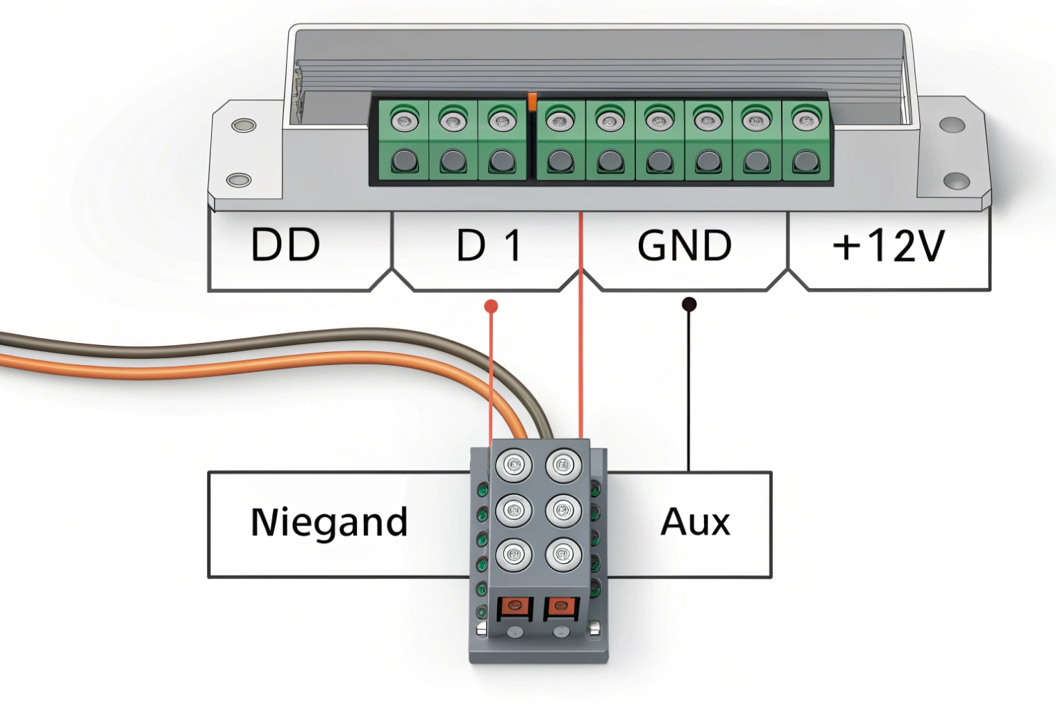
Wire D0 to the controller’s D0 input, D1 to D1, and always share a solid ground. Power the reader with the correct 12V (or spec voltage) and avoid sharing noisy lock power. Use twisted pairs and keep runs clean to reduce noise.
The minimum wiring that must be right
At minimum, the reader needs:
- Power +12V (or +5V depending on model)
- GND
- D0
- D1
Many readers also provide LED control, buzzer control, tamper, and shield/drain. Those extras can be useful, but they are not required for basic card data.
The most important detail is the shared ground. D0 and D1 are referenced to ground. If ground is weak or missing, the controller sees floating pulses. That can look like random reads or no reads.
Open-collector outputs and pull-ups
Many readers use open-collector outputs. This means the controller usually provides pull-up resistors to a logic voltage, often 5V. Some controllers can be sensitive if the pull-up is weak and the cable is long. If runs are long or the environment is noisy, using proper cable and routing matters more than changing settings.
Cable and routing choices that reduce noise
For stable installs:
- Use twisted pair for D0+GND and D1+GND, or use a multi-pair cable with a consistent scheme.
- Keep reader cables away from high-current lock power, motors, and fluorescent ballast lines.
- Use shielded cable in noisy areas, and terminate shield properly at one end as required by site standards.
- Do not power the reader from the same supply that drives a heavy maglock without proper filtering.
Common mistakes that look like “format problems”
Some failures are wiring failures that pretend to be format failures:
- D0 and D1 swapped: controller logs wrong numbers or rejects all.
- Ground missing: intermittent reads, or read only when touching metal.
- Wrong voltage: reader resets or outputs weak pulses.
- Shared noisy power: random reboots, false reads, or lockups.
| Wire | Goes to | Quick symptom if wrong |
|---|---|---|
| +12V | Reader V+ | No power, reboot loops, weak output |
| GND | Reader GND + Controller GND | Random reads or no reads |
| D0 | Controller D0 input | Bits flip, wrong IDs |
| D1 | Controller D1 input | Bits flip, wrong IDs |
| Shield (optional) | Site grounding rule | Noise spikes on long runs |
Once wiring is correct, the next decision is protocol choice. Wiegand works, but it is not the only option now.
What’s the difference between Wiegand, OSDP RS-485, and Ethernet?
Access control is shifting. Many sites still use Wiegand because it is familiar. Yet modern requirements push for secure, manageable reader links.
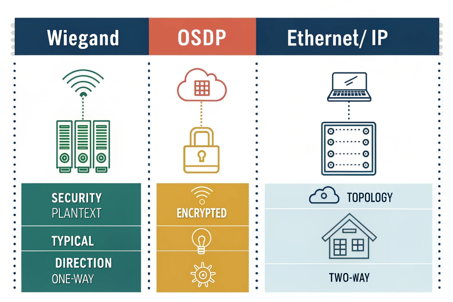
Wiegand is one-way and unencrypted. OSDP over RS-485 is two-way and can be encrypted, with device supervision and remote management. Ethernet readers use IP networking (often PoE) and can support strong security, but need network design and credentials management.
Wiegand: simple, compatible, and exposed
Wiegand is easy. Most controllers support it. Many readers support it. The problem is security and visibility. There is no encryption. There is no reader authentication. There is no way for the controller to ask the reader for status. If the reader is tampered with, the controller might not know.
Wiegand can still be acceptable in low-risk areas if cabling is protected inside conduit and closets. Still, the trend is to treat Wiegand as a legacy link and reduce its exposure. Axis summarizes why Wiegand enables credential interception and replay attacks 5 when the wiring is accessible.
OSDP RS-485: modern control on two wires
OSDP uses RS-485 as the physical layer. It is multi-drop capable and supports addressing, so more than one device can share a bus. It is bidirectional, so the controller can manage LEDs, buzzers, and configurations. With secure channel enabled, OSDP Secure Channel 6 encrypts traffic, which blocks simple sniff-and-replay attacks. It also supports supervision, so the controller can detect disconnects and tamper events in a clearer way.
OSDP does require correct wiring practices: A/B polarity, proper termination, and sane bus topology. Still, once it is set, the stability is very good. If you need practical wiring and termination guidance for long runs, the RS-485 design guide 7 is a useful reference.
Ethernet/IP readers: powerful but needs network discipline
Ethernet readers or IP intercom-style readers connect like any IP device. They often use PoE, TLS, and central management. They can support richer features, but they shift complexity to the network. VLANs, QoS, power budgets, and cybersecurity policy become part of access control.
A practical way to choose:
- Use Wiegand when the site is small and compatibility is king.
- Use OSDP when the site cares about security, supervision, and lifecycle management.
- Use Ethernet when the site already runs strong IP infrastructure and wants centralized control.
| Feature | Wiegand | OSDP (RS-485) | Ethernet/IP |
|---|---|---|---|
| Direction | One-way | Two-way | Two-way |
| Encryption | No | Yes (secure channel) | Yes (TLS options) |
| Cabling | Simple, 3+ wires | Bus wiring, A/B + power | Cat5e/6, PoE |
| Management | Minimal | Remote control and status | Full IP management |
| Typical risk | Sniff/replay | Miswiring/termination | Network security and segmentation |
With protocol choices clear, the next question is how these pieces connect in an IP door system that includes SIP intercoms.
How do SIP intercoms connect Wiegand readers to IP door controllers?
Many door projects want one device at the door that does talk, video, and access. SIP intercoms are often that device. The missing piece is how the reader data reaches the access control logic.
A SIP intercom can connect to a Wiegand reader as an input, then trigger door unlock locally or send events to an IP controller or platform. In other designs, the intercom passes Wiegand through to a separate controller while it only handles audio/video and relay control.
Common integration models used on real sites
There are three patterns that show up again and again.
Model A: Intercom acts as the edge controller
The reader wires into the intercom’s Wiegand input. The intercom checks a local card list or queries a server, then triggers a relay for the lock. This is simple for small sites. It reduces hardware. It also makes the intercom a security-critical device, so the platform and update policy must be strong.
Model B: Intercom + dedicated IP door controller
The reader wires to the door controller, not the intercom. The intercom is used for calling and video. The controller decides access and drives the lock. The intercom can still trigger unlock via dry contact input, Wiegand input, or API calls. This model is strong for enterprise sites because access logic stays in the access platform.
Model C: Intercom bridges reader data to the controller
The reader wires into the intercom, then the intercom outputs Wiegand to a controller, or forwards the credential ID via HTTP API, MQTT, or a platform SDK, depending on system design. This is useful when the reader location is fixed at the intercom, but the controller is inside a protected room.
What to configure so it does not become fragile
For stable deployments:
- Lock the Wiegand bit length in the intercom to match the reader output.
- Decide whether the intercom treats IDs as decimal or hex, and keep the same rule in the backend.
- Set unlock timing and door sensor inputs based on door type.
- If the intercom forwards events, make retries and offline behavior clear, so doors do not fail during WAN dips.
Firewall and network notes that keep support tickets low
SIP signaling and media should be stable, but access control events also need a reliable path. If the intercom talks to a cloud platform, VLAN and firewall rules must allow that traffic. Still, reader-to-intercom wiring stays local, so it is often the easiest part to keep stable.
| Design goal | Best model | Why |
|---|---|---|
| Small site, fast install | Model A | Fewer boxes, fast commissioning |
| High security and audit | Model B | Access logic stays in controller/platform |
| Retrofit with limited cabling | Model C | Uses intercom as a bridge point |
| Future migration to OSDP | Model B or Ethernet reader | Avoids legacy link at the door |
In my experience, the cleanest enterprise design is to keep the controller in a secure closet and keep edge devices simple. Still, many projects accept Model A when budget and speed matter, as long as physical protection is strong.
Conclusion
A Wiegand port sends credential bits on D0/D1 with a shared ground, but it is one-way and unencrypted. Match formats, wire cleanly, and use OSDP or IP designs when security matters.
Footnotes
-
Explains open-collector outputs and why pull-ups are needed to represent logic “high” on a wire. ↩ ↩
-
Practical breakdown of Wiegand pulse timing and bit decoding, plus common failure patterns in real installs. ↩ ↩
-
Shows how access platforms define custom Wiegand bit maps and parity rules for non-default credentials. ↩ ↩
-
HID reference for the standard 26-bit H10301 layout, facility code range, and card number space. ↩ ↩
-
Explains why Wiegand’s unencrypted link enables interception and replay, and why OSDP reduces that risk. ↩ ↩
-
Official OSDP overview describing Secure Channel encryption and supervision benefits compared with legacy reader links. ↩ ↩
-
Practical RS-485 cabling and termination guidance to improve reliability on long, noisy reader runs. ↩ ↩


