
A single unexpected failure can stop an emergency call point in a hazardous area. The worst part is that most failures look “random” until a project audit asks for proof.
MTBF for explosion-proof telephones is usually a predicted reliability number based on a standard model and an environment profile. Real MTBF depends on temperature, power quality, surge exposure, and design choices like derating and coating, plus the evidence package used in the tender.

MTBF for Ex telephones: what it really means in projects
MTBF is often treated like a product “feature,” but it is a reliability estimate with boundaries. A predicted MTBF 1 number comes from a model. The model needs inputs such as component types, stress levels, ambient temperature, and environment class. If the inputs change, the number changes. That is why two vendors can both be honest and still quote very different MTBF values for a similar Ex telephone.
An explosion-proof telephone also sits in a special reality. The product is rugged, but the site can be brutal. Heat rises inside enclosures. PoE loads rise during cold starts. Cable runs pull noise into ports. Lightning surges and switching transients appear more often than in office networks. These external factors drive field failures more than many people expect.
Another point matters in tenders. MTBF is not the same as warranty. MTBF is a statistical measure under assumptions. Warranty is a commercial promise with exclusions. A buyer should use MTBF to compare designs and to plan spares. A buyer should use warranty to plan service risk.
A simple way to make MTBF useful is to link it to a failure rate and a deployment size. If a phone has an annual failure rate of 0.5% in a given environment, then 1,000 phones can produce five repairs per year on average. That kind of planning works better than staring at one big MTBF number.
Predicted MTBF vs field reliability
Predicted MTBF is often higher than what field data shows in heavy industrial sites. This gap is normal. Models assume an environment class and average stress. Field sites can have local hotspots, poor grounding, and surge events that are not “average.” The goal is not to chase a perfect number. The goal is to define a profile that matches the site.
The reliability stack that decides your real outcome
Reliability for Ex telephones with PoE comes from a stack:
- Thermal design and component stress
- Power quality and surge defense
- Corrosion defense (coating, sealing, connectors)
- Firmware stability and watchdog behavior
- Installation quality (shielding, bonding, SPD coordination)
| What drives MTBF most | Typical site symptom | How it shows up in logs | What improves it most |
|---|---|---|---|
| High temperature | Random resets, early PSU failure | Brownout flags, reboot reason | Derating, better thermal path |
| Surge events | Dead ports, no link | PHY failure, PoE PD failure | TVS, GDT/MOV, external SPDs |
| Corrosion and moisture | Intermittent keys, noisy audio | Mic level drift, key bounce | Coating, better seals, material choice |
| EMI and grounding | CRC errors, RTP drops | Interface errors, link renegotiation | Shield bonding, routing, ferrites |
| Firmware edge cases | “Online but not callable” | SIP stack stuck | Watchdog and safe restart logic |
Many tenders ask one line: “MTBF: ____ hours.” The best response is a clear number plus a clear context. The next section explains how to choose the right prediction standard and the right environment profile so that context is defensible.
The moment the standard is clear, the number becomes easier to trust.
Which prediction standard estimates MTBF, and which environmental profile should be used?
A project team can accept a high MTBF only when the method is transparent. “High MTBF” without the model and profile is not useful for procurement.
A good tender response names the prediction standard, the version, the method type, the environment profile, and the reference temperature. Three standards show up most often: MIL-HDBK-217F, Telcordia SR-332, and IEC 61709.
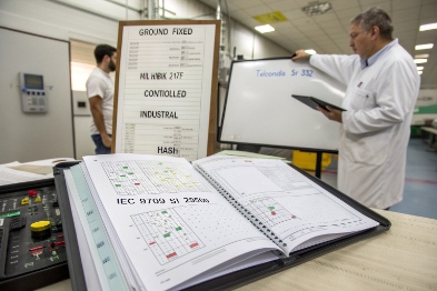
MIL-HDBK-217F: classic, fast, and very assumption-driven
MIL-HDBK-217F 2 is widely used because it is familiar and simple to apply. It supports parts-count and parts-stress approaches. It also uses environment categories that many engineers know. Still, the output depends heavily on the chosen environment class and the stress assumptions. This method is often best for early estimates, comparisons, and quick tender replies when a full stress model is not available yet.
For an Ex telephone, the environment profile should not be “benign office” if the phone is mounted outdoors or near process equipment. A better choice is a fixed industrial cabinet or sheltered outdoor profile, with temperature reflecting the real enclosure conditions.
Telcordia SR-332: strong for telecom-style equipment and program control
Telcordia SR-332 3 is popular for telecom and network equipment because it supports a more modern reliability workflow. It offers different methods depending on what data is available. It is also well suited when a manufacturer has real field return data and wants to combine prediction with operational reality. This fits VoIP products well because the architecture is close to telecom equipment.
A good practice is to use Telcordia when the project requires a reliability report that includes process control, quality levels, and sometimes field data alignment.
IEC 61709: structured reliability reference conditions
IEC 61709 4 provides guidance for reliability prediction and reference conditions. It is often used in a broader IEC-focused compliance culture. It can help teams present failure rate estimates in a consistent format, especially when the buyer prefers IEC documents.
Picking the environment profile: match the plant, not the marketing
The environment profile should reflect:
- Ambient and internal temperature (25°C lab vs 55°C cabinet)
- Vibration exposure and mounting method
- Humidity, salt, and chemical exposure
- Surge exposure (outdoor cable, long runs, lightning zone)
- Duty cycle (always-on PoE, relay loads, beacon loads)
| Standard | Best use in Ex phone tenders | What you must state clearly | Typical pitfall |
|---|---|---|---|
| MIL-HDBK-217F | Quick comparisons, early design estimate | Environment class and temperature | Using “benign” profile for plant installs |
| Telcordia SR-332 | Telecom-grade reporting and lifecycle control | Method type and quality level inputs | Mixing field data without explaining it |
| IEC 61709 | IEC-aligned documentation packs | Reference conditions and assumptions | Treating it as a single fixed number |
In my own quoting work, the safest tender answer includes one primary standard and one sensitivity case. For example: “MTBF predicted at 25°C and at 55°C.” That single extra line reduces disputes later.
Once the model and profile are chosen, the next question becomes practical: what MTBF numbers are realistic at different temperatures for PoE Ex telephones?
What MTBF values are typical at 25°C vs 55°C for Ex telephones with PoE?
Buyers often expect a single MTBF value, but temperature changes the story fast. A PoE Ex telephone has several heat-sensitive parts: DC/DC converters, electrolytic capacitors, magnetics, and power semiconductors. The phone also runs 24/7. That constant stress is very different from a battery device or a handset that sleeps.
Typical predicted MTBF ranges seen in industrial VoIP endpoint classes
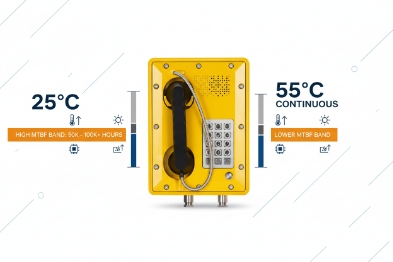
For industrial VoIP endpoints, predicted MTBF numbers often land in the broad range of:
- At 25°C: 100,000 to 300,000 hours (and sometimes higher in “benign” profiles)
- At 55°C: 20,000 to 120,000 hours, depending on thermal design and component choices
These are not universal facts. They are realistic planning ranges that match how temperature accelerates common failure mechanisms 5. Many electronic failure rates rise sharply with temperature. A simple planning rule used in reliability work is that many rates roughly double for each 10°C rise for some mechanisms. A jump from 25°C to 55°C is 30°C. That can mean a several-times increase in failure rate. In that case, MTBF can drop by about 4× to 8× if temperature is the dominant factor.
Why PoE matters in the MTBF calculation
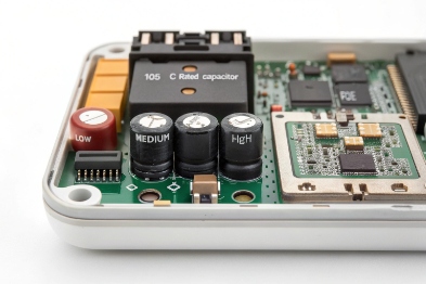
PoE adds constant conversion and heat. The phone takes 48V from the switch and converts it down to lower rails. If the phone also drives loud audio, LEDs, relays, or heaters, peak draw rises. Peak draw creates hot spots. Hot spots shorten life for parts like capacitors and power MOSFETs.
That is why two phones with similar features can show different MTBF. One design may spread heat well and keep capacitor core temperatures low. Another design may trap heat behind a metal partition or close to a sealed enclosure wall.
A practical way to present MTBF in tenders
A tender-friendly format is:
- MTBF at 25°C, stated with environment profile
- MTBF at 55°C, stated with the same profile
- A note stating the number is predicted and that field reliability depends on installation and surge exposure
| Condition | What the number really represents | What a buyer should ask next |
|---|---|---|
| MTBF @ 25°C | Best-case prediction in controlled conditions | Provide 55°C case and assumptions |
| MTBF @ 55°C | More realistic cabinet/outdoor case | Show thermal margin and derating |
| Field AFR estimate | Practical maintenance planning metric | Ask for RMA data and failure modes |
A short personal note helps many buyers understand this. One project used a “high MTBF” phone in a sealed outdoor box. The box ran hot. The phone did not fail from software. It failed from heat stress over time. After adding ventilation and lowering internal temperature, failures dropped without changing the phone model. This is why temperature context belongs in every MTBF discussion.
Temperature is one lever. Design choices and protection choices are the next levers. Those levers decide the gap between predicted MTBF and real field failure rate.
How do derating, conformal coating, and surge protection improve MTBF, and what documents verify it in tenders?
A buyer does not only want a number. A buyer wants confidence that the number will hold in the real plant. That confidence comes from design controls and from the document set.
Component derating: reduce stress, reduce heat, reduce early failures
Derating 6 means using parts below their maximum ratings. It sounds basic, but it has a large effect on power and thermal reliability. The main targets in PoE Ex telephones are:
- Capacitor voltage and ripple margin
- DC/DC converter thermal margin
- Magnetics temperature rise
- Relay contact derating if used for alarms
- TVS and protection parts energy margin
A strong derating plan lowers junction temperature. Lower junction temperature often improves lifetime and reduces drift. It also improves tolerance to real surges and brownouts.
Conformal coating: protect against humidity, salt, and conductive dust
Conformal coating 7 can reduce corrosion and leakage on PCBs in coastal plants, mines, and chemical sites. It is not a magic shield. It must be paired with good connector sealing and good cleaning processes. Some coatings can trap heat or make rework harder. A good design uses coating where it helps and leaves keep-out zones where connectors and test points need service.
In the field, coating mainly reduces intermittent faults. These faults are painful because they waste labor time. A phone might “fail only sometimes” due to moisture or salt. Coating can reduce those cases when the coating choice matches the chemistry.
Surge protection: protect the ports that die first
Surge protection 8 causes sudden failures. In industrial VoIP phones, the ports that often fail under surge stress are:
- Ethernet/PoE front end (PHY, magnetics, PD controller)
- DC input stage (if present)
- Relay I/O lines (if long external wiring exists)
A good surge plan uses layered protection:
- Internal TVS and common-mode control at the port
- Proper earthing and bonding in the enclosure
- External SPD coordination at building entry and near the endpoint on long runs
This approach reduces catastrophic failures and lowers field failure rate even when MTBF prediction models do not fully “see” lightning exposure.
Documents that verify MTBF for tender submission
A serious tender pack usually includes four document types:
1) Reliability prediction report
- Standard used (MIL-HDBK-217F, Telcordia SR-332, or IEC 61709)
- Environment profile, temperature, duty cycle
- Method type (parts count or stress)
- Resulting MTBF and failure rate
2) Parts-count BOM and quality assumptions
- Parts list with categories and quality levels
- Critical components identified (power, protection, connectors)
- Any alternate parts rules and change control notes
3) Stress and derating analysis
- Voltage, current, and thermal margins
- Hot-spot temperature estimate at 55°C ambient
- PoE power budget and peak load behavior
- Notes on capacitor lifetime assumptions
4) Warranty and service terms
- Warranty duration and exclusions
- RMA and replacement process
- Recommended spares for large deployments
- Optional extended warranty terms for mission-critical sites
| Tender document | What it proves | What the reviewer checks |
|---|---|---|
| Reliability report | MTBF method and assumptions | Standard version, profile, temperature |
| Parts-count BOM | Inputs to the model | Completeness and part classes |
| Stress/derating analysis | Real thermal and electrical margin | Hot spots, capacitor margin, PoE peaks |
| Surge strategy summary | Defense against real plant threats | Port protection, SPD coordination plan |
| Warranty terms | Commercial risk handling | Coverage clarity and response time |
For large industrial deployments, a small extra step helps. Provide an “MTBF is predicted” statement and add a practical field planning metric such as an expected annual failure rate range under defined conditions. That gives the project team a way to plan spares and maintenance. It also reduces conflict later when conditions differ from the model profile.
Conclusion
MTBF is only meaningful with a stated standard, environment, and temperature. Derating, coating, and surge defense reduce real failures. A strong tender pack proves the method and the service commitment.
Footnotes
-
MTBF Mean Time Between Failures; a statistical measure of the expected reliability of a repairable system or component. ↩
-
MIL-HDBK-217F U.S. military handbook for reliability prediction of electronic equipment, focusing on component stress analysis. ↩
-
Telcordia SR-332 Reliability prediction procedure for electronic equipment, widely used in telecommunications industries. ↩
-
IEC 61709 International standard providing failure rates for electronic components and guidance for reliability prediction. ↩
-
failure mechanisms The physical or chemical processes that lead to the failure of a device or component, often accelerated by heat. ↩
-
Derating The practice of operating a component at less than its rated maximum limit (e.g., voltage, power) to extend its life. ↩
-
Conformal coating A thin polymeric film applied to printed circuit boards to protect components from moisture, dust, and chemicals. ↩
-
Surge protection Devices or methods used to shield electrical equipment from voltage spikes and transient surges. ↩


