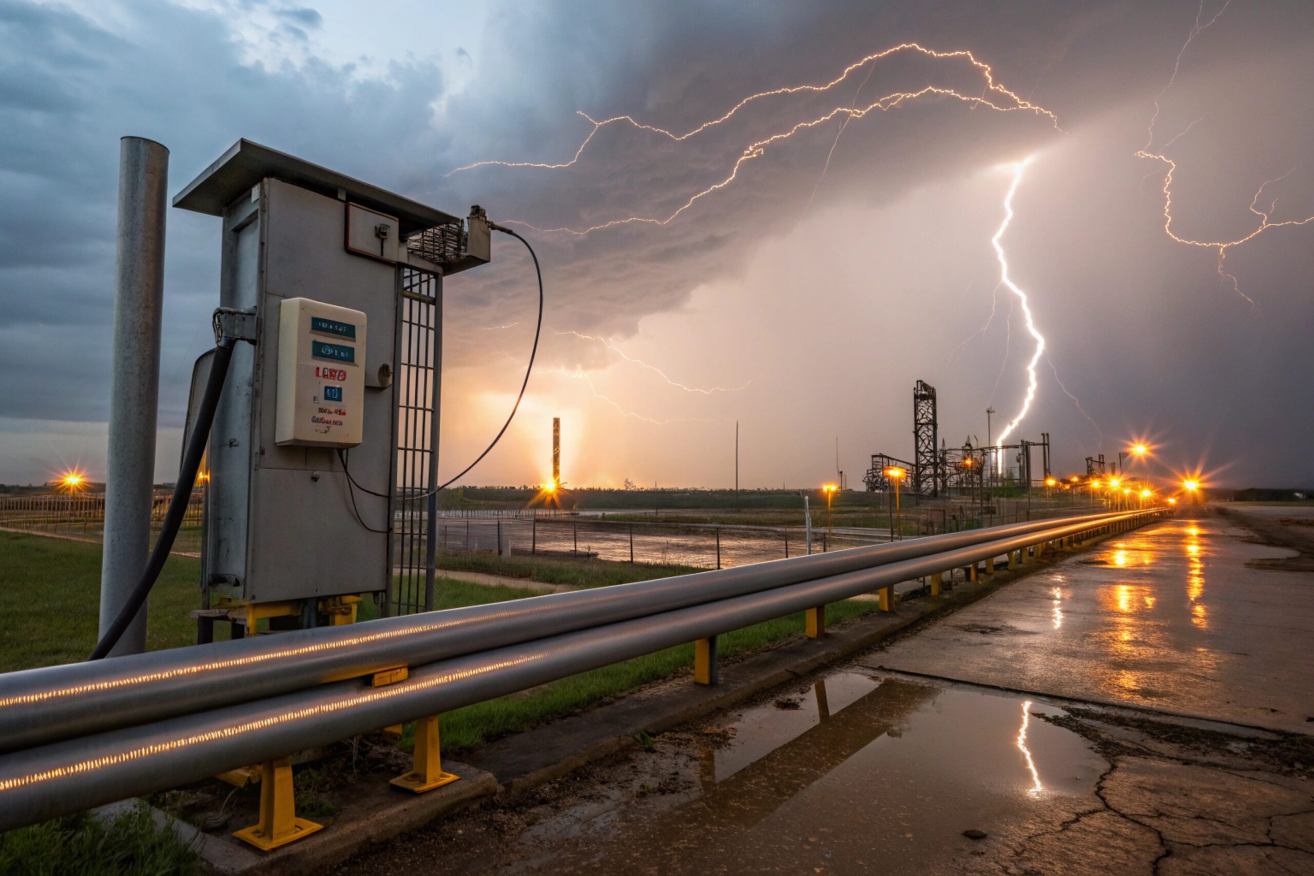
Lightning and switching surges can kill an Ex phone without leaving obvious damage. Then the SOS point fails right when the plant needs it most.
The “required” lightning protection level depends on exposure, cable routes, and your site lightning protection system. Use staged SPDs plus surge immunity targets so the phone survives real faults, not only lab checks.

A practical way to size lightning protection for Ex telephones?
Start with exposure, not the Zone label
Zone 1/2 tells you the ignition risk. It does not tell you the surge energy. Lightning risk comes from where cables run, how far they run, and whether they enter from outdoors. A phone mounted on an offshore deck with a 200 m outdoor cable is a very different case from a phone inside a refinery building with metal tray and bonding. The first step is a simple exposure map: indoor vs outdoor, cable length, and how many building boundaries the cable crosses.
Use staged protection so no single SPD does everything
One SPD 1 at the phone is not enough if the surge enters at a panel. One SPD at the panel is not enough if a long cable re-radiates energy near the device. A stable design uses three stages: a strong entry SPD, a distribution SPD, and a fine clamp near the endpoint. The goal is to “step down” energy, then clamp voltage to what the phone electronics can survive.
Design around the phone’s weak points
Ex phones usually fail at four interfaces: Ethernet/PoE, 24 VDC power, relay/I/O lines, and long external antenna-like cable shields. Each interface needs the right SPD type and the right bonding reference. If the bonding is long or corroded, the SPD cannot protect well.
| Exposure case | Typical surge entry path | Staged SPD idea | Main acceptance goal |
|---|---|---|---|
| Indoor, short runs | Switching surges in panels | Type 2 at panel + device clamp | No resets, no port damage |
| Outdoor on structure | Direct/near lightning coupling | Type 1+2 at entry + Type 3 at device | Keep service after storm |
| Inter-building cables | Ground potential rise + coupling | Protect at both ends + shield bonding | No blown PHY/I/O ports |
A good plan ends with a proof test on site: paging under load, then a controlled surge test record from vendor evidence, then a yearly inspection routine. With this mindset, the details below become easy to choose and easy to defend during audits.
If this feels like a lot, it is still simpler than replacing devices after every storm and trying to explain why alarms went silent.
Which standards apply—IEC 61643-11 SPDs, ITU-T K.21/K.45, and IEC 61000-4-5 surge immunity?
Lightning protection fails when teams mix standards without a clear job for each one. One standard defines the SPD itself. Another defines how the device must survive surges.
Use IEC 61643-11 for low-voltage power SPDs, ITU-T K-series for telecom-style resistibility guidance on ports and lines, and IEC 61000-4-5 to define surge immunity test levels and waveforms for the phone and its interfaces.
IEC 61643-11: the SPD product baseline for power
IEC 61643-11 2 is used to classify and test SPDs used on low-voltage power systems. It helps answer basic procurement questions: is this a Type 1, Type 2, or Type 3 device, and what waveform is it designed to handle. It also gives you the language you need for coordination: maximum continuous operating voltage, nominal discharge current, and voltage protection level.
IEC 61000-4-5: what “surge immunity” really means
IEC 61000-4-5 3 defines surge test waveforms and how immunity testing is performed. This is the standard that turns a marketing claim into a test plan. It is also the quickest way to compare two phones: ask what level and what ports were tested. A phone that survives a surge on its Ethernet port is different from a phone tested only on its power input.
ITU-T K.21/K.45: resistibility thinking for telecom ports
The ITU-T K-series 4 is widely used in telecom environments to describe overvoltage and overcurrent stresses and resistibility requirements. For plant buyers, the practical value is simple: it provides a common language for surge tests on communication interfaces and helps explain why port protection matters even when the power system is protected.
What to request from vendors and integrators
Ask for test evidence that is easy to read: which port, which waveform, which level, and whether the device still worked after the test. Also ask whether the SPD selection was coordinated with the test levels.
| Standard | What it answers | What to ask for in a project file | Common mistake |
|---|---|---|---|
| IEC 61643-11 | “Is this the right SPD type for power?” | Type, ratings, Up, coordination notes | Buying Type 3 only and calling it “lightning” |
| IEC 61000-4-5 | “Will the phone survive this surge?” | Port list + test levels + pass criteria | Testing only one interface |
| ITU-T K.21/K.45 | “How tough are telecom-style ports?” | Port resistibility statement + protection concept | Assuming Ethernet is always “industrial hardened” |
The most stable audits happen when these standards are used as a system set: IEC 61643-11 for the SPD hardware, IEC 61000-4-5 for immunity evidence, and ITU-T K-series thinking for port protection discipline.
What kA/kV ratings are needed for PoE, 24 VDC power, and I/O lines in Zone 1/2?
Numbers look precise, but lightning is not polite. Ratings must match exposure and architecture, not just a single “Zone 1” label.
Select kA/kV ratings by exposure tier: indoor short runs need lower surge energy handling, while outdoor and inter-building runs need higher. Zone 1/2 affects where you can mount SPDs, not the surge energy itself.
Think in three exposure tiers
A simple tier model keeps decisions consistent across sites:
-
Tier A (indoor, bonded steel, short cable runs): switching surges dominate. Nearby lightning is possible but lower coupled energy.
-
Tier B (outdoor on the same structure): nearby lightning coupling is common. Long trays and masts act like antennas.
-
Tier C (between buildings or long outdoor runs): ground potential rise and big induced surges are realistic.
PoE (Ethernet) protection targets
PoE ports are sensitive. Ethernet magnetics and PHY chips die fast when surge energy reaches them. For PoE, the SPD must protect both data pairs and power pairs without breaking link quality. In practice, the most useful selection criteria are:
-
surge current rating per pair (kA class, depending on exposure)
-
very low clamping voltage for the data lines
-
low capacitance so it does not harm signal integrity
-
proper shield bonding strategy if shielded cable is used
24 VDC power and I/O protection targets
24 VDC lines can carry high surge energy because they often run long distances and connect to cabinets with different ground references. The SPD must clamp low enough to protect electronics but high enough to avoid nuisance conduction during normal operation. I/O lines are often the weakest. A small transient can punch through a digital input.
A practical selection approach is:
-
Higher kA devices at the panel or building entry
-
Lower kA, lower clamping devices near the phone or I/O termination
| Line type | Typical placement | SPD type idea | Rating approach that fits most plants |
|---|---|---|---|
| PoE Ethernet | At building entry + near phone (outdoor runs) | Data/PoE SPD matched to link speed | Tier A: lower kA; Tier B/C: higher kA per pair, low clamping |
| 24 VDC power | DC distribution panel + near endpoint | DC SPD with low Up | Tier A: moderate; Tier B/C: higher energy handling at panel, fine clamp at device |
| Relay/I/O lines | Cabinet I/O marshalling + near device if long | Signal line SPD | Lower kA but very low clamping, placed close to input |
Why “kV” is not the whole story
A kV test level describes the voltage of the applied surge in a lab method. The real damage depends on source impedance, waveform, and how your cable and bonding spread energy. This is why staged SPDs and bonding rules matter more than chasing one big number.
When a site asks for “the required kA/kV,” the best answer is a tiered bill of materials that matches the cable map. That is also easier to maintain, because spare parts follow the same tier logic.
Should Type 1/2/3 SPDs be staged at panels and devices while preserving Ex d/e compliance?
A staged SPD plan can protect well, but a bad install can break Ex compliance. Safety inspection will catch it, and operations will not accept it.
Yes. Stage Type 1/2/3 SPDs at the right points, but keep SPDs in suitable enclosures and locations so you do not compromise Ex d flamepaths or Ex e clearances, and use certified glands and bonding methods.
Stage at the right physical boundaries
A stable staging plan uses real boundaries:
-
Building/service entry: where lightning energy first enters the facility
-
Distribution panel: where surges spread into branch circuits
-
Device vicinity: where electronics need the final clamp
Type 1 SPDs are used where high-energy lightning currents can enter. Type 2 SPDs protect distribution circuits. Type 3 SPDs are close protection for sensitive equipment.
Keep Ex compliance intact
Explosion-proof (Ex d) 5 enclosures rely on flamepaths and controlled mechanical joints. Adding components inside the Ex d housing without certification is a compliance risk. A safer pattern is:
-
Put higher-energy SPDs in a safe area panel or in an approved field cabinet outside the hazardous zone.
-
If protection must be placed inside the hazardous area, use a certified approach such as an Ex e terminal/junction enclosure designed for added components, or use a certified inline protector that is approved for that environment.
Cable entries matter as much as boxes. Certified glands must match cable type and diameter. Seal integrity must be kept. Corrosion-resistant materials should be used in sour or offshore sites.
If Type 3 is too strong, it can fail early because it absorbs too much energy. If Type 1/2 is too weak, Type 3 sees high stress. Coordination is a procurement job, not only an install job. Ask for a coordination note from the SPD supplier or from the system integrator.
| Stage | Typical location | What it protects | Ex-focused checklist |
|---|---|---|---|
| Type 1 | Main entry / LPS bonding point | High-energy lightning currents | Keep outside Ex zone when possible |
| Type 2 | Sub-distribution / PoE switch cabinet | Switching + residual lightning | Short bond to PE bar, clear labeling |
| Type 3 | Near phone or near I/O termination | Sensitive ports and electronics | Use certified enclosure/glands, no flamepath compromise |
One more rule that prevents long-term failures
Every SPD needs a reliable disconnect and an inspection method. Add status indicators where technicians can see them. Add spare cartridges where the design allows. Then document replacement and proof testing. A “protected” system that no one can maintain becomes unprotected within one storm season.
Which grounding, bonding, and cable shielding practices ensure lightning protection and long-term reliability?
Many lightning problems are not “too much energy.” They are “bad impedance.” A great SPD on a long skinny ground wire protects poorly.
Use equipotential bonding, short low-impedance earth connections, proper shield termination, and consistent cable routing so SPDs have a solid reference and surges do not travel through electronics.
Bonding: give the surge a better path than your phone
Lightning energy takes every path available. The goal is to provide a preferred path that bypasses sensitive electronics. That starts with equipotential bonding 6:
-
bond cabinets, trays, conduits, and structural steel
-
bond PA masts and camera poles into the same network
-
bond the Ex phone 7 mounting bracket where required by site rules
Bonding must be low impedance. Wide straps and short runs beat long round wires. Corrosion control matters too. A bond that is green and loose is not a bond. Use suitable washers and surface preparation so metal-to-metal contact stays stable.
Cable shielding: terminate shields correctly and consistently
Shields work only when they are terminated correctly. The best practice in lightning and EMC work is usually 360° termination at entry points, not long pigtails. For Ethernet, use shielded cable only when the plant standard supports proper shield bonding and the endpoint hardware supports it. For long outdoor runs, metal conduit or armored cable with proper bonding can reduce coupling.
Routing and separation: reduce surge coupling before it starts
Do not route phone cables alongside VFD motor cables. Keep separation from lightning down conductors and high-current feeders. Cross power lines at right angles when needed. Avoid large loops in cable routing because loops pick up induced voltage.
Surge reference: bond SPD earth to the same bar as the protected equipment
A surge protector clamps voltage to its reference. If that reference floats away during a surge, the clamped voltage at the device can still be high. This is why short bonding to the local earth bar matters. For inter-building cables, protect both ends. Ground potential rise 8 can drive current from one building to the other through your telecom cable.
| Practice | Why it works | Quick field check |
|---|---|---|
| Short, wide bonding straps | Lower inductance, better surge path | Bond length is short and direct |
| Clean metal contact points | Reduces corrosion and resistance | No paint under lugs, no loose bolts |
| 360° shield termination | Avoids pigtail inductance | Clamp-style termination at entry |
| Separate from VFD/motor cables | Less induced noise and surge coupling | Dedicated tray or spaced runs |
| Protect both ends of long cables | Stops ground rise current | SPD present at each building boundary |
| Label and inspect bonds/SPDs | Keeps protection alive over time | Inspection checklist is used and signed |
The long-term reliability part
Lightning protection is not a one-time install. It is a maintenance item. Add these routines:
-
inspect glands and seals for water ingress
-
inspect bond points for corrosion
-
check SPD status indicators and replace failed modules
-
verify NTP and syslog time so event logs stay trusted after storms
A system that is bonded, staged, and inspected will keep emergency phones alive far longer than a system that relies on one “big” protector 9.
Conclusion
Choose lightning protection by exposure tier, then stage SPDs and bonding so surges bypass electronics. Keep Ex compliance intact, and treat SPDs and bonds as maintained safety assets.
Footnotes
-
Surge Protection Device designed to limit transient overvoltages and divert surge currents. [↩] ↩
-
International standard for low-voltage surge protective devices connected to power systems. [↩] ↩
-
Standard defining immunity requirements and test methods for electrical equipment against surges. [↩] ↩
-
ITU-T recommendations for resistibility of telecommunication equipment to overvoltages and overcurrents. [↩] ↩
-
Explosion protection type relying on a robust enclosure to contain internal explosions. [↩] ↩
-
Electrical connection putting various exposed conductive parts at substantially the same potential. [↩] ↩
-
Hazardous area telephone designed to operate safely in environments with explosive gases or dust. [↩] ↩
-
Phenomenon where large currents flow into the earth, raising the potential of the ground grid. [↩] ↩
-
Maintenance strategy ensuring lightning protection systems remain effective over their operational life. [↩] ↩


