Many Ex phone rollouts fail for a boring reason: the line cannot feed enough current, or the ring voltage collapses at the far end. The phone looks “dead.”
Most analog explosion-proof telephones are designed to operate on the same loop-current reality as classic POTS: typically ~20–50 mA in normal service, with a practical working window around 20–60 mA when the line feed and cable conditions are healthy. The exact result depends on loop resistance, the FXS/PSTN current limit, and any series devices like barriers or surge modules.

Loop current is a system budget, not a single number
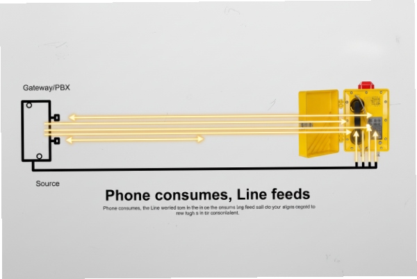
Loop current is created by the line feed, not by the phone
An analog Ex telephone (FXS-end device) does not “generate” loop current. It closes the loop when it goes off-hook, and the line feed (PSTN or FXS port) provides DC voltage and current. That is why the same telephone can work perfectly on one gateway and behave badly on another.
In most industrial projects, the line feed is not a public PSTN exchange. It is an IP PBX with FXS cards or an analog gateway (ATA). These devices often have configurable current limits and ring parameters. A conservative integration plan treats loop current as a budget:
-
Line feed DC voltage (often around the -48 V family in on-hook state)
-
Source impedance/current limit inside the FXS/PSTN
-
Cable loop resistance (distance, conductor size, joints, corrosion)
-
Any extra series resistance (surge protectors, isolators, barriers, terminal blocks)
-
The phone’s off-hook DC impedance and internal electronics load
What “good” looks like for an Ex phone in the field
A stable installation normally shows:
-
The phone draws enough loop current to keep audio stable and DTMF clean.
-
The off-hook voltage at the phone stays in a normal band (not collapsing to near zero).
-
Ring voltage at the phone stays high enough under load to trigger ring detect and ring output.
-
Surges are diverted at a defined boundary without adding too much series loss.
A simple planning table for procurement and FAT
| Item | What to capture | Why it matters |
|—|—|—|
| FXS/PSTN line feed | current limit, on-hook voltage, ring Vrms/Hz | sets the available electrical budget |
| Cable loop | length, conductor size, junction count | drives resistance and ring loss |
| Phone load | off-hook current draw, ringer type, REN | determines how “hard” it is to feed and ring |
| Added devices | SPDs 1, barriers, isolators | can add resistance and reduce ring margin |
| Acceptance targets | loop current band + ring Vrms at phone | makes FAT repeatable |
If these are written down early, commissioning becomes a check, not a troubleshooting session.
The next sections answer the exact questions that usually decide success: real loop-current range, minimum off-hook voltage and loop resistance, protection strategy, and ring detect at remote low-margin sites.
Is the operating range 20–60 mA under real PSTN loads?
A site can claim “PSTN compatible,” but the phone still cuts out if the gateway current limit is low or the copper loop is long.
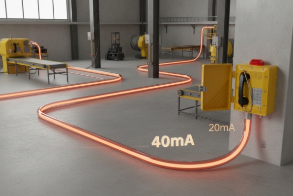
Yes, 20–60 mA is a practical operating window for many analog Ex telephones in real service. In normal conditions, many lines sit closer to ~20–50 mA. The safe approach is to design so the phone still works when the loop current drops near the low end.
Why 20–60 mA is a useful engineering band
In classic telephony, loop current commonly lands in a middle band, not at the extremes. Modern FXS ports also tend to target a stable loop current, but different vendors pick different limits. Remote sites often have higher loop resistance, so the current naturally drops.
For an explosion-proof telephone, the practical risk is not that it draws “too much.” The risk is that the line feed cannot supply enough current once cable losses and added components are included. That causes:
-
low transmit level
-
noisy audio
-
unreliable DTMF
-
random call drops when the line feed toggles states
How to check your site’s “real” loop current
A useful check is simple and fast:
1) Put the phone off-hook.
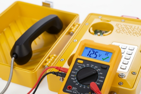
2) Measure DC current in series with one leg (at a safe test point).
3) Measure DC voltage across Tip/Ring at the phone terminals.
4) Repeat during worst-case conditions: longest run, most junctions, hottest enclosure.
What changes the number in real projects
| Factor | Effect on loop current | Typical symptom |
|—|—|—|
| Long cable loop | reduces current | weak audio, DTMF errors |
| Corroded joints | reduces current | intermittent drops |
| Current-limited FXS | clamps current low | “works sometimes” behavior |
| Added series modules | reduces current | stable off-hook but poor ring |
| Ex i barriers (if used) | can reduce current and ring | phones ring weakly or fail to seize |
Recommendation that avoids most failures
A solid design does not assume the phone will always see 40 mA. It assumes it might see ~20 mA on the worst line. If the phone and gateway are both stable at that low end, the installation tends to be reliable. If the phone needs high current to stay stable, it is a mismatch for long-loop industrial sites.
What are the minimum off-hook voltage and loop resistance limits?
A phone can show “some current” and still fail because the loop voltage collapses under load, especially with long copper and extra series devices.
Many analog phones operate with an off-hook voltage commonly in a single-digit to low-teens volt range at the device, while drawing tens of milliamps. Typical loop resistance in classic service often falls in the few-hundred-ohms to ~1–2 kΩ range, but long industrial runs and added components can exceed that, so a measured loop budget is safer than assumptions.
Off-hook voltage: what matters for Ex phones
The phone needs enough DC voltage at its terminals to keep:
-
the microphone and audio amplifier stable
-
the keypad/DTMF generator stable
-
any internal line interface circuitry stable
If the voltage at the phone drops too low under load, the phone may still seize the line, but voice quality and DTMF reliability get unstable. This shows up most on long loops and with gateways that have low feed voltage or aggressive current limiting.
Loop resistance is the sum of both conductors plus all junctions and terminals. It rises with:
-
longer runs
-
smaller conductor size
-
poor terminations
-
wet or corroded junction boxes
-
extra series protection devices
Even when the DC loop resistance is acceptable, the AC ring signal can be worse because the loop has capacitance and leakage that hurts ringing more than talk.
A planning table you can use without guessing
| Item to define | Practical way to define it | Why it helps |
|—|—|—|
| Minimum loop current for acceptance | choose a target like “works at ~20 mA” | covers worst cable cases |
| Minimum off-hook voltage at phone | define an acceptance floor in FAT | avoids “seizes but unusable” installs |
| Maximum loop resistance | measure the worst run, then add margin | stops remote failures |
| Added series losses | list all SPDs/barriers and their impact | prevents ring collapse surprises |
A realistic engineering habit for remote sites
For remote tank farms and long pipe racks, a line simulator or a long test spool during FAT saves time. The goal is to prove that the phone remains stable at the lowest expected current and voltage conditions, not only on a short bench cable.
How is overcurrent or surge protection implemented?
Lightning and switching surges are common on long outdoor runs. A protection plan that only relies on the phone’s internal parts is usually weak.
Overcurrent and surge protection is best implemented in layers: line-feed current limiting inside the FXS/PSTN equipment, dedicated telecom surge protection at a defined boundary bonded to the equipotential earth, and internal phone protection components sized to survive residual surges without overheating or compromising Ex sealing.
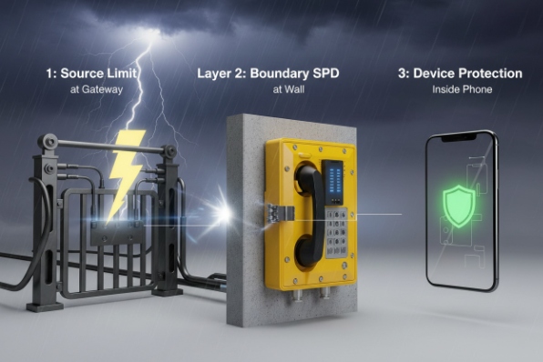
Layer 1: line-feed current limiting (built into FXS/PSTN)
Most FXS line interfaces already limit DC current. That protects the line feed electronics and reduces fault energy if the cable is shorted. It does not protect well against fast surge energy from lightning, because lightning is not a slow DC fault.
Layer 2: boundary surge protection (the most important layer)
The best place for a telecom surge protector is usually:
-
building entry point
-
marshalling cabinet in a safe area
-
a well-bonded boundary panel before the line enters a hazardous-area run
This device should be bonded to the site equipotential network with a short, low-impedance path. Long “earth tails” reduce protection quality. The protector should be selected for telecom line use and installed so it does not add excessive series resistance that kills loop current or ringing.
Layer 3: device-side residual protection
Inside many industrial phones, protection can include:
-
gas discharge tubes (GDT) for high-energy surge diversion
-
TVS diodes for fast clamping
-
series impedance elements to shape surge energy
The internal design must also respect thermal limits and the certified build, because components that heat under fault conditions can affect temperature classification and long-term reliability.
A practical protection selection table
| Protection element | What it does | What it can hurt if misused |
|—|—|—|
| GDT (surge diversion) | handles larger surge energy | poor bonding makes it ineffective |
| TVS (fast clamp) | protects sensitive electronics | too much leakage can load the line |
| PTC/fuse | limits sustained current | added series resistance can reduce loop current |
| Boundary SPD | main surge energy control | wrong rating can add loss or fail early |
In ATEX areas, bonding and cable entry discipline matter as much as the SPD part number. A perfect SPD is wasted if the cabinet is not bonded correctly or if the cable entry leaks and corrodes the terminations.
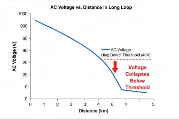
Does ring detect work at low-current remote sites?
Remote sites often complain: “dial works, but ringing is unreliable.” That is normal when ring voltage collapses at the far end.
Ring detect depends mainly on the AC ring signal at the phone (Vrms, frequency, cadence) and the phone’s ringer load, not on off-hook loop current. Low-current remote sites often also have high loop impedance, which reduces ring voltage under load, so ring may fail even if off-hook talk current is acceptable.
Why ring fails first on long loops
Ringing is harder than talking because:
-
the ring generator has a finite source impedance
-
long loops add resistance and capacitance
-
the ringer load (REN) draws AC current
-
poor joints distort the waveform
So a phone might seize and dial fine, yet never ring reliably because the ring voltage at the phone drops below the ring-detect threshold.
What to measure for ring reliability
For each worst-case line:
-
measure ring voltage at the phone terminals while ringing (under load)
-
confirm ring frequency (commonly around 20–25 Hz in many systems)
-
confirm cadence matches the PBX profile
-
confirm the gateway “ring trip” works (ring stops immediately on answer)
Practical fixes that work in most remote installations
| Symptom | Likely cause | Fix that usually works |
|—|—|—|
| No ring at far end | ring voltage collapses on long loop | ring booster, higher ring Vrms, lower REN phone |
| Weak or intermittent ring | marginal ring detect threshold | lower ring frequency, reduce ringer load |
| Ring stops too late or too early | ring trip detection issues | adjust gateway ring-trip settings |
| Works on short cable only | loop impedance too high | shorten run, larger conductor, reduce junction count |
| Ring breaks after adding SPD | SPD adds loss or wrong wiring | use telecom SPD designed for low insertion loss |
A FAT method that prevents onsite surprises
During FAT, simulate the worst loop:
-
add a long cable spool or line simulator
-
set the actual country ring profile on the gateway/PBX
-
test at least 20 ring cycles
-
confirm ring detect, ring trip, and DTMF stability
If the site is truly remote and the loop is long, a safer architecture is to place the FXS source closer (in a boundary cabinet) and transport the call over SIP/fiber to that cabinet. That changes the copper loop from “kilometers” to “meters,” and ring reliability improves dramatically.
Conclusion
Plan loop current and ringing as a full loop budget. Prove low-end stability in FAT, protect the line at boundaries, and measure ring Vrms at the phone on the worst run.


