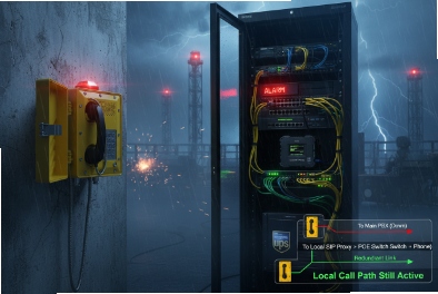
Packet loss turns an emergency call into broken words. In refineries and mines, that can mean the right action starts too late.
The best strategy mixes codec-side concealment, adaptive jitter buffers, and network QoS. Opus FEC can help at moderate loss, while RTP redundancy helps with short bursts, but QoS and priority queuing still do most of the real work.

A practical packet-loss playbook for industrial Ex SIP phones
Start with the workflow, not the codec
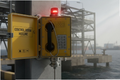
An explosion-proof telephone is often part of an emergency chain. That means the target is not “hi-fi audio.” The target is “intelligible speech under stress.” So the first step is to separate traffic types:
-
emergency duplex calls 1 need the lowest delay and the highest protection.
-
PAGA and paging need stable timing and predictable volume, even if delay is slightly higher.
-
Routine calls can accept slightly lower priority.
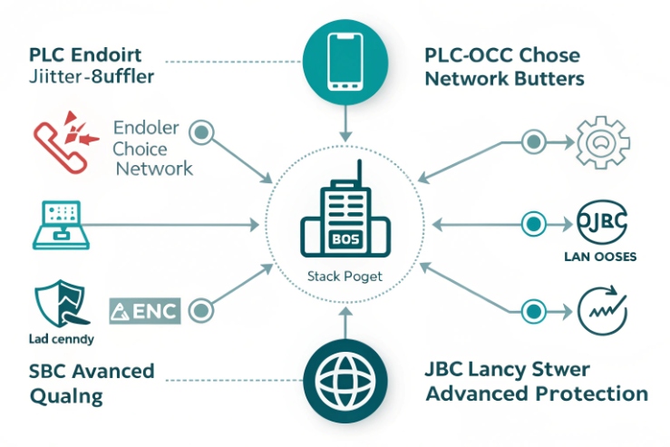
Use a layered defense
The implementation of packet loss compensation 2 works best when it is layered:
1) Network protection: VLAN, DSCP, priority queue, and rate control.
2) Transport protection: redundancy or FEC only where it makes sense.
3) Endpoint protection: PLC and a jitter buffer 3 tuned for the site.
A lot of plants try to “fix loss with codec tricks” while the switch is still dropping packets. That approach fails during congestion, because redundancy still needs bandwidth.
Set targets that are easy to test
Targets should be written in a way that field teams can validate with a capture and switch counters.
| Item | Good target for emergency calls | Acceptable for paging | Why it matters |
|---|---|---|---|
| One-way delay | under 150 ms preferred | under 250 ms typical | clarity and turn-taking |
| Jitter | under 30 ms typical | under 50 ms typical | buffer can stay small |
| Random packet loss | under 1% preferred | under 3% | PLC can mask small loss |
| Burst loss | avoid > 2 consecutive frames | avoid > 3 frames | redundancy helps only for short bursts |
Treat burst loss differently from random loss
PLC and Opus FEC are good at masking isolated losses. They struggle when loss comes in bursts. Burst loss usually points to queue drops and congestion. So the playbook should include a step that checks switch queue drops and uplink utilization before changing codec settings.
A small story to keep in mind: in one offshore project, the “codec problem” vanished after moving paging traffic out of the same queue as CCTV streams. The phone firmware never changed.
Keep reading. The next sections break down PLC and jitter buffers, codec choices, RTP redundancy and FEC, and the tuning knobs that keep latency low.
In the end, the best packet loss strategy is the one that operators forget about because it just works.
A simple next step is to run a 10-minute stress test on the worst link, then tune only after the network behavior is visible.
Should PLC and adaptive jitter buffers be enabled, and what loss and jitter targets keep SIP and RTP intelligible in industrial sites?
Loss and jitter often hide until shift change, storms, or a busy network window. Then the audio breaks and the blame lands on the phone.
Enable PLC and use an adaptive jitter buffer. Aim for under 1% loss and under 30 ms jitter for clean duplex voice. With strong PLC and good QoS, 3% loss can still be usable, but emergency calls should not rely on that.

Why PLC should be on by default
PLC is the phone’s last line of defense. It fills short gaps when a packet is missing. For G.711 4, many implementations use waveform repetition and smoothing. For modern codecs like Opus, PLC is built into the decoder. In field terms, PLC helps most when:
-
loss is random and isolated
-
packets are late but not consistently late
-
the link has occasional microbursts
PLC does not fix consistent drops caused by congestion. It only hides the symptom for a moment.
Why adaptive jitter buffers 5 fit industrial networks
A fixed jitter buffer is simple, but industrial networks do not behave like lab networks. A link can be clean for hours, then jump when a radio link fades or when a backup path activates. An adaptive buffer can grow when needed and shrink when stable. The tradeoff is added delay. That is why the buffer must have limits.
A good field approach is:
-
start buffer around 30–60 ms
-
allow growth up to a ceiling such as 120 ms for duplex calls
-
allow a higher ceiling for paging if the site accepts it
What targets keep speech intelligible
The targets below are realistic and easy to align with site acceptance:
-
One-way delay: keep it low enough that users do not talk over each other.
-
Jitter: keep it low enough that the buffer does not grow too large.
-
Loss: keep it low enough that PLC is not “working nonstop.”
| Condition | What users hear | Likely cause | Best fix |
|---|---|---|---|
| 1–3% random loss | small roughness, still clear | mild congestion or radio fades | QoS + PLC + modest buffer |
| 5% loss | choppy words, stress rises | queue drops | fix queueing, avoid oversubscription |
| 10–15% loss | broken phrases, repeats | severe congestion or bad link | reroute, add bandwidth, survival path |
| Jitter spikes > 50 ms | robotic audio, gaps | path changes or microbursts | buffer ceiling + switch tuning |
A good maintenance practice is to log loss and jitter by time of day. If the worst window is predictable, that is a network capacity problem, not a codec problem.
Does Opus with in-band FEC and longer ptime outperform G.711 with RFC 2198 redundancy at 5–15% loss?
When loss rises, the first instinct is “add redundancy.” That can work, but it can also double bandwidth and make congestion worse.
Opus with in-band FEC often performs better than G.711 with redundancy at moderate loss because it uses less bitrate and can recover important speech content with limited overhead. At 10–15% loss, both approaches struggle unless QoS and link capacity are fixed, but redundancy can still help with short burst losses.

What Opus in-band FEC really does
Opus can embed a low-bitrate recovery version of the previous audio into a later packet. This helps when a packet is lost and the next packet arrives. So Opus FEC has two practical implications:
-
it works best when loss is isolated, not long bursts
-
it adds a one-packet dependency, so ptime choices matter
For emergency calls, Opus is attractive on constrained links because it can deliver good intelligibility at lower bandwidth than G.711. Lower bandwidth also reduces the chance of congestion drops, which is often the real win.
What RFC 2198 redundancy does
RFC 2198 redundancy sends extra copies of earlier audio frames alongside the current frame. In practice, one redundant copy protects you against losing one packet, as long as the next packet arrives. It is simple and effective for short losses, but it increases bandwidth. If the link is already congested, redundancy can increase drops and create a loop of failure.
Why 5–15% loss is a danger zone
At 5% loss, good PLC and a stable jitter buffer can still produce usable speech. At 10–15%, the call becomes stressful unless the audio path has strong protection and the loss is not bursty. In real plants, loss at that level usually points to a design issue: oversubscribed uplinks, poor Wi-Fi, unstable radio, or misconfigured QoS.
| Strategy | Strength at 5% random loss | Behavior at 10–15% | Cost |
|---|---|---|---|
| Opus + PLC | good clarity | degrades but may stay usable in short windows | low bandwidth |
| Opus + in-band FEC | better recovery on isolated loss | still struggles on bursts | medium bandwidth |
| G.711 + PLC | acceptable if loss is low | degrades fast | high bandwidth |
| G.711 + RFC 2198 | helps short bursts | may overload links | higher bandwidth |
A practical rule: if the site sees 10% loss, fix the network first. Use Opus FEC or redundancy as a safety net, not as the main plan.
Can RFC 5109 FEC or RTP redundancy plus QoS and priority queuing protect emergency calls on congested links?
When a link is congested, every added byte fights for space. Protection can help, but it must be paired with strict priority handling.
Yes, but only in the right order. QoS and strict priority queuing should protect RTP first. RTP redundancy or FEC can then reduce the impact of short loss bursts. RFC 5109-style FEC is more common in gateways and media relays than in endpoints, so many sites deploy it at the SBC or paging gateway.

Start with QoS that actually enforces priority
Emergency voice needs protected latency and low loss. The network plan should include:
-
DSCP marking for RTP and SIP
-
trust boundary at the access switch
-
a strict priority queuing 6 for voice RTP
-
policing so voice cannot starve everything else
-
call admission rules so paging does not flood the link
If RTP is not placed in a protected queue, no FEC method will rescue the call during peak congestion.
Where redundancy and FEC fit
After QoS, you can add media-layer protection:
-
RTP redundancy is simple and can be effective for one-packet losses.
-
RFC 5109-style FEC can recover lost packets based on parity across a protection group, but it adds overhead and requires both ends to support it.
In many industrial deployments, the best place for these features is not the phone. It is the SBC or media gateway that controls RTP. That keeps endpoint configuration simple and makes behavior consistent across models.
Protect emergency calls without breaking paging
A common risk is that paging audio gets the same priority as emergency duplex calls. Paging can be constant and high duty cycle. It can also hide congestion signals. The clean separation is:
-
emergency duplex RTP in the strict priority queue
-
paging multicast in a high queue, but not strict
-
routine voice in a normal voice class
| Traffic type | Recommended treatment | Why |
|---|---|---|
| Emergency call RTP | strict priority + low jitter buffer | intelligibility and fast turn-taking |
| Emergency signaling | high priority but below RTP | keep setup fast |
| Paging multicast | high priority, rate-limited | stable pages without starving calls |
| CCTV and bulk data | lower priority | avoid crushing voice |
A good field proof is a “worst minute” test: create controlled load, start a normal page, then place an emergency call. The emergency call must remain clear without long delay growth.
How should ptime, jitter buffer, and comfort-noise and VAD be tuned to minimize latency while maintaining clarity for PAGA and paging?
Tuning often goes wrong because one setting is changed and the rest is ignored. Then the system feels delayed, or it clips the first word of every page.
For most industrial SIP phones, 20 ms ptime is the safest baseline. Use an adaptive jitter buffer that starts around 30–60 ms and caps at a level that keeps one-way delay under control. For paging and PAGA, avoid aggressive VAD that can clip syllables, and use comfort noise only when it supports the workflow.

ptime tradeoffs in harsh networks
ptime controls how much audio is in each RTP packet. Smaller ptime reduces packet impact when one packet is lost, but it increases packet rate and overhead. Larger ptime lowers overhead, but each loss is a bigger audio hole and it can add extra algorithmic delay.
A practical baseline:
-
Duplex emergency calls: 20 ms ptime
-
Paging and PAGA: 20–30 ms ptime if the platform supports it cleanly
In high-loss radio links, 30 ms can reduce overhead and may help stability, but it increases the “damage per packet loss.” So it should be used only if the network is already protected and stable.
Jitter buffer settings that keep latency reasonable
A jitter buffer adds delay by design. The goal is to absorb variation without creating a long talk delay. A field-friendly setup:
-
minimum buffer: 30 ms for clean LAN, 50–60 ms for WAN
-
maximum buffer: 120 ms for duplex calls
-
maximum buffer: 150–200 ms for paging if the site accepts it
Paging can tolerate slightly higher delay because it is one-way. But it cannot tolerate gaps and choppiness. So paging often prefers “more buffer” over “less delay.”
VAD and comfort noise rules for paging
VAD saves bandwidth by not sending packets during silence. That can be good on low-bandwidth links. But it can also clip the start of speech, which is painful in paging and PTT. For PAGA and paging:
-
avoid aggressive VAD on the talker side
-
avoid gating that cuts the first syllable
-
use comfort noise 7 carefully so users know the link is alive
| Scenario | ptime | Jitter buffer | VAD and CN recommendation |
|---|---|---|---|
| Emergency duplex call | 20 ms | 30–120 ms adaptive | VAD optional, CN optional |
| Dispatch PTT paging | 20 ms | 50–150 ms adaptive | VAD off or gentle, CN low |
| Wide-area PAGA | 20–30 ms | 80–200 ms | avoid clipping, stable playout |
| Congested link survival | 20 ms | tighter cap + QoS | reduce paging duty cycle |
A small personal note: a mine site once blamed “slow paging.” The real issue was a huge jitter buffer cap plus VAD clipping. After tightening buffer ceilings and disabling aggressive VAD on paging zones, pages felt instant again.
Conclusion
Use QoS first, then PLC and adaptive jitter buffers, then FEC or redundancy as a safety net. Tune ptime and VAD differently for emergency calls and paging.
Footnotes
-
Two-way simultaneous communication essential for real-time emergency responses in hazardous sites. ↩ ↩
-
Strategies to mask or restore missing audio data packets in VoIP systems. ↩ ↩
-
A technique used to handle packet delay variation and ensure smooth audio playout. ↩ ↩
-
A high-bandwidth legacy pulse code modulation codec used widely in telecommunications. ↩ ↩
-
Dynamic buffers that adjust their size based on changing network conditions. ↩ ↩
-
Ensures that time-critical voice traffic is processed before all other data packets. ↩ ↩
-
Synthetic background noise added during silence to reassure users the link is active. ↩ ↩