Unstable SIP calls and random reboots often come from noise on the Ethernet line. In a hazardous area, that becomes a safety and uptime problem.
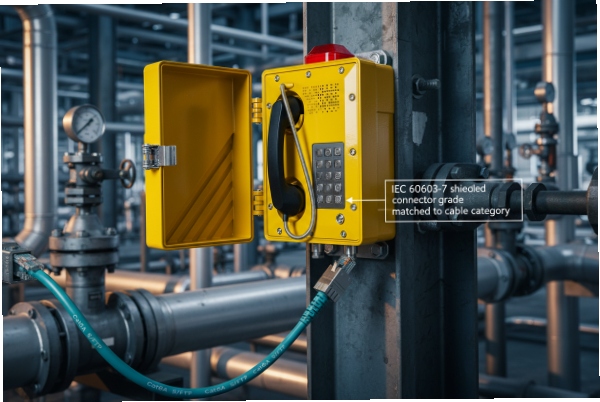
Use the same Ethernet shielding rules as any industrial VoIP endpoint: specify an IEC 60603-7 shielded 8P8C connector grade that matches your cable category, then control shield bonding, QoS, and surge protection at installation.

A practical selection rule for RJ45 shielding on Ex telephones
Start from connector and cabling standards, not the “RJ45” nickname
“RJ45” is used as a casual name for an 8P8C modular connector. For procurement, the useful standard language is:
-
Connector performance category (Cat5e/Cat6/Cat6A/Cat8.x) under the IEC 60603-7 1 family
-
Cabling performance class (Class D/E/EA/… in ISO/IEC 11801 2 or ANSI/TIA-568 3 families)
A clean specification ties them together: Cat6A cable 4 + Cat6A shielded connector, with a shield termination method that preserves 360° contact.
Pick shielding based on EMI severity and bonding quality
Shielding only helps when the shield is bonded correctly. If the cable shield is “pigtail grounded” with a long drain wire, the high-frequency impedance is high and the shield becomes less effective. If the shield is bonded 360° at the entry and to the connector shell, the shield is actually doing its job.
In refineries and chemical plants, the EMI sources are real: VFD drives 5, large motors, switching power supplies, lightning coupling on long outdoor runs, and shared cable trays. In those sites, screened cable plus correct bonding is a safer default than trying to “see if UTP works.”
A simple spec table that works in EPC documents
| Site condition | Recommended connector/cable | Why it is the safer choice |
|---|---|---|
| Office-like comms room | UTP Cat5e/Cat6 may work | low EMI and short runs |
| Process unit with VFDs | Shielded Cat6A (S/FTP or F/UTP) + shielded 8P8C | better margin against noise |
| Outdoor long runs (tray/pipe rack) | Shielded Cat6A + surge protection 6 at both ends | reduces lightning-induced issues |
| PoE++ 7 high power endpoints | Cat6A cable rated for PoE heat + shield continuity | avoids heating and voltage drop |
| Mixed vendors and unknown switch QoS | Shielded cable + strict bonding + testing | reduces “it depends” failures |
The goal is not to “make it shielded.” The goal is to make it predictable: stable link, stable audio, and no surprises during commissioning.
If the project needs a single sentence for a tender, this one works: “Industrial Cat6A screened cabling (ISO/IEC 11801 Class EA) with shielded IEC 60603-7 compliant 8P8C connectors, bonded 360° at the enclosure entry.”
That sets you up for the next decision: whether shielded connectors and STP/FTP are truly required on the job, or only recommended.
A good answer should separate compliance needs from best practice.
Are shielded 8P8C connectors and STP/FTP cables required?
EMI problems do not show up in a quiet lab. They show up after the plant starts, when drives switch and lightning storms hit.
Shielded 8P8C connectors and STP/FTP cable are not required just because a phone is explosion-proof. They are required when the site EMI, bonding rules, and network reliability targets demand them.
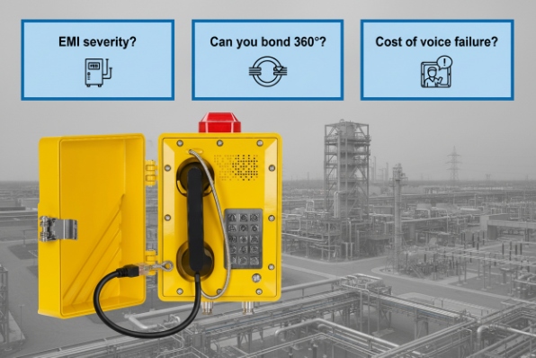
Use three questions to decide “required” vs “nice to have”
1) How harsh is the EMI?
If the cable shares tray space with power cables, VFD outputs, or long outdoor runs, shielded cable is often the low-risk choice.
2) Can the shield be bonded correctly?
If installers cannot do 360° bonding at the entry and maintain shield continuity through patch panels, a “shielded cable” can become a half-measure. In that case, the fix may be routing and separation, not only shielding.
3) What is the cost of a voice failure?
If the telephone is used for emergency calling, “works most days” is not acceptable. A small cost increase for screened cabling is usually justified.
Connector choice matters as much as cable choice
It is common to see screened cable terminated into an unshielded plug, then connected to a plastic coupler. That breaks the shield path. If the cable is shielded, the connector and coupler should be shielded too, and the shield should have a low-impedance path to the enclosure bond.
Recommended “minimum” and “robust” options
| Approach | Cable | Connector | Best-fit projects |
|---|---|---|---|
| Minimum acceptable | U/UTP Cat6 | Unshielded 8P8C | short indoor runs, low EMI |
| Robust industrial default | F/UTP Cat6A or S/FTP Cat6A | Shielded 8P8C, metal shell | plants with drives and noise |
| Outdoor / lightning-exposed | Shielded Cat6A + surge protection at both ends | Shielded connector + bonded entry | pipe racks, tank farms |
| High PoE power | Cat6A with PoE heat rating | Shielded 8P8C rated for PoE | PoE++ devices, bundled cables |
In many hazardous-area projects, the Ethernet cable enters a metal enclosure through a certified gland. That entry point is also the best place to bond the shield. If the shield is bonded there, shielded cabling has real value. If it is not bonded, the difference between UTP and STP can be much smaller than expected.
So, “required” is not about Ex certification. It is about risk, EMI, and installation control. If the project cannot control routing and bonding, shielding becomes a weak guarantee.
That leads into the most important installation detail: how to ground the shield to the metal enclosure without creating new problems.
How is cable shield grounded to the metal enclosure?
A shield that is grounded wrong can be worse than no shield. It can act like an antenna, and it can add ground noise into the PHY.
Bond the shield with a short, wide, 360° connection at the enclosure entry, then keep shield continuity to the RJ45 metal shell. Avoid long drain-wire “pigtails” for high-frequency bonding.
Use 360° bonding at the entry point
The most reliable method is an EMC-style gland or clamp that grips the cable screen around its full circumference and bonds it directly to the metal enclosure. This reduces impedance at high frequency. It also keeps the shield path short and mechanically stable.
If the phone enclosure uses a certified Ex cable entry, the gland must match the Ex/IP requirement first. After that, select a version that also supports shield termination, or use an internal 360° clamp inside the certified entry chamber, depending on the product design.
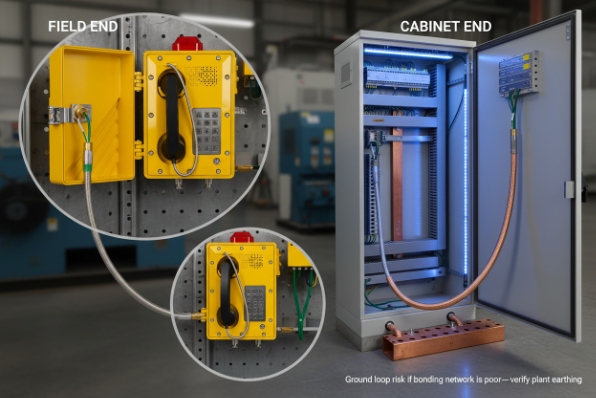
Decide “both ends bonded” versus “one end bonded” with real plant rules
For high-frequency digital links like Ethernet, bonding at both ends is often best for EMI control. The risk is a ground loop if the plant bonding network is poor. The practical solution is not to “float the shield.” The solution is to ensure good equipotential bonding and correct earthing practice across cabinets.
A common approach that works well:
-
Bond the cable shield to the telephone enclosure at the entry (360°)
-
Bond the shield at the switch cabinet end as well (patch panel or switch ground reference)
-
Ensure cabinet bonding is correct and low impedance
Keep the shield path continuous
Shielding works as a chain. The chain breaks when any of these happens:
-
shielded cable terminated into unshielded plug
-
plastic coupler between patches
-
shield bonded only by a thin drain wire
-
painted enclosure surface prevents metal-to-metal contact
A grounding method table for installers
| Method | EMI result | Typical mistake | Recommendation |
|---|---|---|---|
| 360° gland / clamp at entry | best | clamp on painted surface | clean bare metal bond |
| Drain-wire pigtail to PE stud | weak at HF | long pigtail length | use only if no other option |
| Shield bonded at one end only | mixed | reduces HF shielding | use only if bonding network is poor |
| Shield bonded both ends + good bonding | best | missing cabinet bonding | verify equipotential bonding |
When the shield is bonded correctly, Ethernet links become more stable under bursts of noise. That stability also helps PoE behavior, because PoE negotiation and power delivery are sensitive to link drops.
Next is a common confusion in audits: whether EMI rules change just because the device is installed in a hazardous area.
Does EMI compliance change in hazardous areas?
Many teams assume “Ex certified” means the device is also “EMC compliant.” That assumption can cause surprises in CE documentation reviews.
Hazardous-area (Ex) requirements focus on ignition risk, while EMC requirements focus on emissions and immunity. The environment is industrial, but the EMC rules do not become “special” just because the site is hazardous.
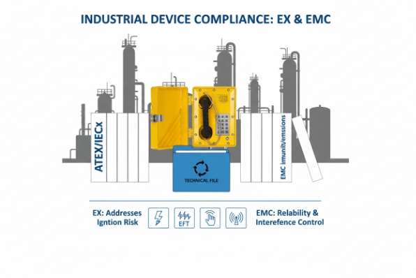
Treat Ex and EMC as two compliance tracks
Explosion protection is validated under the Ex standards and certification system. EMC is validated under the EMC standards and the applicable market directive requirements. In EU projects, it is normal to have separate conformity evidence for:
-
Low Voltage / Safety (if applicable)
-
Radio (if the product has wireless functions)
So the EMC expectation does not vanish in a hazardous area. If anything, plants often demand stronger immunity because the EMI sources are stronger.
What “industrial EMC” usually means for a telephone
For an industrial wired VoIP endpoint, the typical EMC target is:
-
strong immunity to surges, EFT, ESD, and radiated fields
-
controlled emissions so it does not interfere with other equipment
The practical implication is simple: cabling, shielding, and surge protection are part of EMC compliance in the field. A phone can pass lab EMC tests and still fail on site if installation is poor.
Special caution when intrinsic safety is involved
If the telephone contains intrinsic safety 10 circuits or connects to intrinsically safe accessories, the EMC discussion must include the IS parameters and the separation rules. Noise can couple into long accessory cables. That is not “EMC compliance changes.” It is “the design is more sensitive,” so routing and bonding need more discipline.
An audit-friendly documentation table
| Document item | What it proves | Why procurement should ask for it |
|---|---|---|
| EMC test summary (industrial) | immunity/emissions evidence | avoids “Ex only” misunderstanding |
| Installation guide (shield, bonding, SPD) | field assumptions | reduces site failures |
| Declared cable types | supported cabling | prevents weak substitutions |
| Change-control for OEM/ODM | configuration stability | keeps EMC behavior consistent |
A simple rule keeps teams aligned: Ex certification keeps the product safe from ignition. EMC compliance keeps the product reliable in the plant. You need both.
That reliability topic leads into surge protection, because the most common “mystery resets” are often surge-related, not only EMI.
Are surge protectors rated for PoE and lightning?
If the phone is outdoors or tied into long cable runs, surge energy can couple into the Ethernet. PoE makes this more demanding because the SPD must pass DC power without choking the link.
Use Ethernet/data-line surge protectors that explicitly support the PoE power level in use and are tested to telecom/signaling surge standards. For lightning-prone sites, protect at the building entry and near the device, and bond the SPD to the same grounding system.
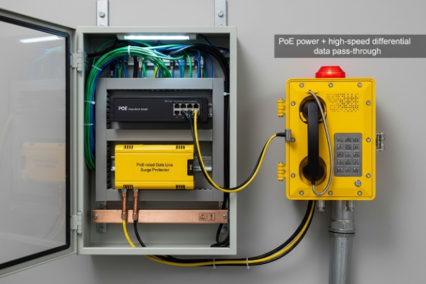
PoE changes what “surge protector” must handle
A PoE-capable SPD must pass:
-
the Ethernet high-speed differential signals
-
the PoE DC current without overheating or excessive voltage drop
If the project uses higher-power PoE (such as PoE++), the SPD must be rated for that current. Otherwise, it can become a hot spot and a failure point. The safest step is to specify the PoE class and require the SPD rating to match it.
Two-stage protection is more reliable than one device
For long outdoor runs, a single SPD near the phone may not be enough. A better pattern is:
-
SPD at the building/cabinet entry (where the cable first bonds to the local earth)
-
SPD near the powered device if the cable run is long and exposed
This reduces surge stress at the device and stabilizes the network during storms.
Ex installation safety: place the SPD correctly
If the telephone is installed in a hazardous area, the SPD should typically be installed in:
-
a safe area cabinet, or
-
a certified Ex enclosure or certified arrangement approved by the site
The SPD itself is not automatically Ex-rated. The installation method must keep the hazardous-area integrity intact. The best approach is to keep surge devices in the safe-side cabinet whenever possible.
A surge protection selection table
| Scenario | PoE level | SPD requirement | Installation note |
|---|---|---|---|
| Indoor short runs | PoE or no PoE | basic data SPD optional | focus on bonding |
| Outdoor tank farm run | PoE+ / PoE++ | PoE-rated Ethernet SPD | protect both ends |
| Lightning-prone region | any | SPD with strong surge rating | bond to low-impedance earth |
| High-noise industrial | any | SPD + shielding + separation | treat as an EMC package |
The key is to treat surge protection as part of the Ethernet design, not an afterthought. When surge, shield bonding, and VLAN/QoS are all consistent, Ex telephones behave like reliable plant assets instead of “fragile IT devices.”
Conclusion
Choose shielded RJ45 by IEC connector grade and cable class, bond shields 360° to the enclosure, keep EMC documentation separate from Ex, and use PoE-rated Ethernet SPDs for outdoor and lightning-exposed links.
Footnotes
-
[IEC standard specifying dimensions and mechanical requirements for 8-way connectors.] ↩
-
[International standard for generic cabling systems in commercial premises.] ↩
-
[North American telecommunications standard for commercial building cabling.] ↩
-
[Augmented Category 6 cable designed for 10 Gigabit Ethernet speeds.] ↩
-
[Variable Frequency Drives that control motor speed but generate electrical noise.] ↩
-
[Measures protecting systems from voltage spikes and lightning.] ↩
-
[High-power Power over Ethernet standard delivering up to 100W.] ↩
-
[EU directives describing equipment allowed in explosive atmospheres.] ↩
-
[Concept ensuring devices work without causing or suffering interference.] ↩
-
[Explosion protection technique restricting electrical energy to safe levels.] ↩


