A hazardous-area phone can look “certified” and still be the wrong choice. Then maintenance gets blocked, and the site loses a trusted emergency voice path.
Ex i telephones fit best where explosive gas can be present often, where live intervention is likely, and where limiting electrical energy is safer than relying on a heavy flameproof enclosure.

A simple decision method for choosing Ex i in real plants?
Ex i is about energy control, not “stronger metal”
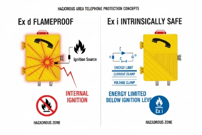
Ex i (intrinsically safe) 1 is a protection concept that limits electrical energy so ignition cannot occur, even with certain faults. This is different from Ex d 2, which contains an internal ignition. Ex i is often the cleanest choice when the site wants a circuit that stays safe by design, and when the device may need frequent work without heavy mechanical steps. In real projects, Ex i becomes attractive in three situations. First, the area can be Zone 0 3 or has a high chance of explosive atmosphere presence, so the operator wants the most conservative concept. Second, technicians may need to swap a handset, test a line, or check terminals more often than expected, and the site wants fewer “open flameproof enclosure” events. Third, the phone is part of a wider intrinsically safe ecosystem already used for instruments, sensors, and call points. In that case, Ex i keeps the same wiring rules, labeling, and inspection habits.
Where Ex i can be the wrong tool
Ex i can be a poor fit when the phone needs high power for very loud ringers, big beacons, long accessory wiring, or heavy relay loads. It can also be a poor fit when the site has limited control of wiring discipline, because Ex i depends on correct barriers, correct parameters, and correct cable separation. In my own deployments, Ex i works best when the plant already runs disciplined IS loops and has clear tagging and inspection routines.
| Question to ask | If “yes,” Ex i is usually a good fit | If “no,” consider other concepts |
|---|---|---|
| Can explosive atmosphere be present frequently? | Zone 0/1 thinking, higher risk tolerance | Mostly Zone 2 or non-hazard areas |
| Will technicians intervene often? | Frequent checks, replacements, testing | Rare intervention, sealed for years |
| Do you need high power at the endpoint? | Basic voice and limited outputs | High-SPL horns, heavy beacons, long I/O |
| Is the site good at IS wiring discipline? | Strong labeling and separation habits | Mixed trades, weak segregation control |
The next step is to get specific about where Ex i fits in the hazardous map, and why people choose it for live maintenance and frequent intervention.
Which hazardous areas suit Ex i—Zone 0/1 gas IIC with live maintenance or frequent intervention?
A phone is only useful if it can be serviced and trusted. In high-risk zones, service rules can block quick fixes if the protection concept is not matched to how the site works.
Ex i is a strong choice for Zone 0 and Zone 1 gas areas, including demanding IIC gases, when the site expects frequent intervention or wants safer live maintenance behavior. Ex i can also be used in Zone 2, but the value is highest where risk and intervention rate are both high.
Why Zone 0 pushes projects toward Ex i
Zone 0 means an explosive gas atmosphere is present continuously or for long periods. In practice, few protection concepts are suitable there without strict limits. Ex i is often selected because it controls ignition energy at the circuit level. This aligns well with conservative safety philosophies. It also reduces the need to rely on heavy mechanical containment for every small electrical fault scenario.
Why Zone 1 often benefits from Ex i in “high-touch” locations
Zone 1 4 areas can have explosive atmosphere sometimes during normal operations. If the phone is mounted at sampling points, loading connections, or operator stations where people interact often, intervention can be common. Ex i helps when the operator wants a design that is safe by limiting energy, and that can align with quicker service practices. Still, “live maintenance” is not a free pass. The site still needs to follow procedures, and the equipment must be installed “as certified.” …Ex i mainly reduces ignition risk from electrical energy, but it does not remove all permit and safety steps.
Gas group and temperature class still matter
Ex i devices still have gas group 5 and temperature class markings. IIC and a suitable T-rating matter if hydrogen or other demanding gases are part of the process risk. …Temperature class selection should follow the site’s hazardous area dossier. The safest approach is to match the strictest requirement for the intended locations so later process changes do not force rework.
Practical placement examples
-
Inside analyzer shelters and near sampling systems where intervention can be frequent.
-
Operator call points near process equipment where technicians may need to test devices often.
-
Areas with high gas presence probability where the plant wants maximum margin and strict control.
| Location type | Why Ex i fits | What to confirm |
|---|---|---|
| Zone 0 call point | Highest atmosphere presence | Ex i marking + correct barrier system |
| Zone 1 operator station | Frequent human interaction | Maintenance workflow and spare strategy |
| High gas group areas (IIC) | More demanding ignition behavior | Marking includes IIC + T-rating |
Once the location fit is clear, the real engineering work begins. Ex i success depends on entity parameters and correct barriers. That is where many projects fail during inspection.
How are entity parameters verified—Ui, Ii, Pi, Ci, Li matching with galvanic isolators or Zener barriers?
When Ex i fails in the field, it often fails on paperwork and wiring, not on electronics. …The core is entity parameter matching.
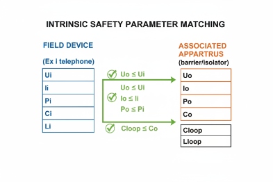
Entity parameter verification checks that the barrier or isolator output limits (Uo, Io, Po) do not exceed the device input limits (Ui, Ii, Pi), and that total cable capacitance and inductance stay within allowed (Co/Ci and Lo/Li) values for the gas group.
The matching logic in plain words
Intrinsic safety is built on “maximum possible energy.” The field device (the phone or the IS interface) has limits it can safely accept: Ui, Ii, Pi. The barrier or galvanic isolator has limits it can output: Uo, Io, Po. The rule is simple:
-
Uo must be ≤ Ui
-
Io must be ≤ Ii
-
Po must be ≤ Pi
Then there is the cable. …Cables store energy as capacitance and inductance. The barrier defines maximum allowed external capacitance and inductance (Co and Lo). …The device has internal capacitance and inductance (Ci and Li). The cable adds Cc and Lc. The rule is: -
(Ci + Cc) must be ≤ Co
-
(Li + Lc) must be ≤ Lo
This is where long cable runs and wrong cable types hurt. It is also where high gas groups like IIC can reduce allowable energy storage, so limits become tighter.
…Zener barriers vs galvanic isolators
-
Zener barriers are simple and cost-effective, but they depend heavily on a solid, low-impedance earth. …That earth must be inspected and maintained.
-
…Galvanic isolators provide isolation and often simplify earthing concerns. They can be easier for modern plants that want cleaner segregation between control systems and field wiring.
The best choice depends on the site’s grounding quality, inspection habits, and cabinet standards.
What to document for acceptance
Entity parameter matching 6 should be documented in a short calculation sheet for each loop or each standard loop type:
-
Barrier model and parameters (Uo, Io, Po, Co, Lo)
-
…Device parameters (Ui, Ii, Pi, Ci, Li)
-
Cable type and length, and its C and L per meter
-
Resulting totals and pass/fail
| …Item | Barrier / Isolator side | Device side | What the inspector checks |
|---|---|---|---|
| Voltage | Uo | Ui | Uo ≤ Ui |
| Current | Io | Ii | Io ≤ Ii |
| Power | Po | Pi | Po ≤ Pi |
| Capacitance | Co | Ci + Cc | (Ci + Cc) ≤ Co |
| Inductance | Lo | Li + Lc | (Li + Lc) ≤ Lo |
If this matching is done once and templated, large deployments become repeatable. If it is skipped, the project gets stuck during commissioning.
After parameter matching, wiring rules decide day-to-day reliability. Ex i wiring is safe only when cable identification, separation, and barrier placement stay consistent over time.
What wiring rules apply—blue IS cabling, cable separation, earthing, and safe-area barrier placement for inspections?
In Ex i systems, good wiring practice is not “nice to have.” …It is part of the protection concept. Without discipline, later maintenance can accidentally break compliance.
Ex i wiring typically uses blue identification for IS circuits, physical separation from non-IS wiring, controlled earthing (especially for Zener barriers), and safe-area barrier placement in accessible cabinets for inspection and testing.
…Blue identification and labeling
Many sites use blue cable jackets 7 or blue markers for intrinsically safe circuits. The key is quick recognition. A technician should know in one glance which cables are IS. Labels should include loop ID, area, and barrier channel. This prevents accidental mixing during shutdown work.
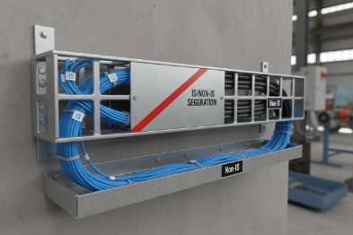
…Separation and segregation
IS circuits should be separated from non-IS power and signal wiring. This is done with:
-
Separate trays or conduits, or
-
Divider systems inside trays, and
-
Clear spacing rules in cabinets
The reason is simple. Non-IS circuits can carry higher energy and induced noise. If they couple into IS circuits, the safety assumptions can be violated. Even when safety is not violated, noise can cause call quality problems and false triggers on inputs.
Earthing rules: extra care with Zener barriers
Zener barriers need a dependable earth path because they clamp energy to earth during faults. That means:
-
A designated earth bar for IS barriers
-
Short, robust earth connections
-
Periodic inspection of bonding and resistance
Galvanic isolators reduce dependence on a perfect earth, but they do not remove the need for good bonding practices in the cabinet.
Safe-area barrier placement for inspections
Barriers and isolators are best placed in the safe area cabinet:
-
Easier access for inspection
-
Lower risk during maintenance
-
Better control of wiring and documentation
This also aligns with practical plant operations. Cabinets in safe areas are easier to keep clean, dry, and labeled.
| Wiring rule | What to do | Why it matters | Quick inspection check |
|---|---|---|---|
| IS identification | Blue cable or blue markers | Prevents accidental mixing | Visual check along route |
| Segregation | Separate trays or dividers | Protects IS assumptions | Cabinet and tray audit |
| Barrier location | Safe area cabinet | Easier testing and control | Verify barrier tagging |
| Earthing | Short, solid earth path | Required for Zener barriers | Earth bar integrity check |
When wiring rules are stable, integration becomes much easier. The final question is how to connect Ex i endpoints into a modern SIP system without breaking IS rules.
How do I integrate Ex i endpoints—IS analog handset via FXS barrier to SIP gateway, or fiber backhaul with safe-area power?
Integration is where many teams get confused. They want “a SIP Ex i phone,” but Ex i and Ethernet power features can conflict if not designed carefully. The clean solution is often to keep active network and power equipment in the safe area, then extend an intrinsically safe circuit to the hazardous area.
Two common integration patterns work well: (1) an Ex i analog endpoint using an IS barrier into an FXS port on a SIP gateway or IP PBX, and (2) fiber backhaul to a nearby safe-area cabinet that powers and controls the SIP endpoint while the hazardous-area side stays within certified IS limits.
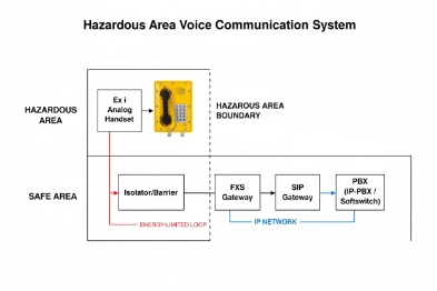
Pattern 1: Ex i analog endpoint + barrier + FXS to SIP gateway
This is the most common and easiest to approve.
-
The hazardous area has an Ex i handset or Ex i telephone station designed for IS loops.
-
The field circuit runs back to the safe area cabinet.
-
…A Zener barrier 8 or galvanic isolator 9 limits energy.
-
The safe area uses an FXS gateway (or an analog card on an IP PBX) to present a standard analog line.
-
The SIP system sees this as an analog extension, but it can still use modern routing, recording rules, and hotline logic.
Why this works:
-
Intrinsic safety stays in the field loop where it is proven and inspectable.
-
SIP features stay in the safe area where power and network are stable.
-
Maintenance is simpler because the barrier cabinet is accessible.
Pattern 2: Fiber backhaul and safe-area power with controlled hazardous-side endpoints
This pattern is used when long distances or EMC issues make copper hard, or when the site needs stronger immunity.
-
Fiber runs along the plant route to reduce lightning and EMI coupling.
-
A safe-area cabinet near the hazardous boundary hosts the powered network equipment (switch, gateway, SBC node).
-
From there, the hazardous-side connection uses an approved Ex concept path, which may still be an IS circuit for controls, or a certified field device depending on the product concept.
This approach is strong for wide sites like tank farms and jetties. It reduces copper exposure and makes network design more stable.
How to choose between the two patterns
-
If the goal is fast approval and repeatability, choose the FXS + barrier design.
-
If distance and EMI are major problems, add fiber and move cabinets closer to the field, while keeping the hazardous wiring within certified limits.
| Integration option | What sits in the hazardous area | What sits in the safe area | Best for |
|---|---|---|---|
| IS analog + FXS | Ex i handset/endpoint | Barrier + FXS gateway + SIP PBX | Simple, repeatable deployments |
| Fiber + safe-area node | Minimal field wiring | Switch/gateway on UPS near boundary | Long runs and heavy EMI zones |
A small personal note from field work: the fastest projects are the ones that keep “smart” gear in safe cabinets and keep hazardous-area endpoints simple. That reduces both downtime and inspection friction.
Conclusion
Ex i telephones are best for Zone 0/1 and high-risk areas where energy limitation and frequent intervention matter. Success depends on correct entity matching, disciplined IS wiring, and safe-area integration through gateways and fiber. Can also be used in Zone 2 10.
-
Detailed comparison of Intrinsically Safe vs Explosion Proof protection concepts. ↩
-
Explanation of Explosion Proof (Ex d) containment principles. ↩
-
Definition of Zone 0 hazardous areas and where they occur. ↩
-
Definition of Zone 1 hazardous areas and typical examples. ↩
-
Guide to Gas Groups (IIA, IIB, IIC) and their impact on equipment selection. ↩
-
Technical article on calculating Entity Parameters for IS loops. ↩
-
Industry standards for blue cable jackets in intrinsically safe wiring. ↩
-
Pros and cons of Zener barriers vs Galvanic isolators. ↩
-
Deep dive into Galvanic Isolator technology and benefits. ↩
-
Overview of Zone 2 classification and equipment requirements. ↩


