Mixing camera brands should be easy, yet feeds vanish, PTZ fails, and alarms never arrive. ONVIF exists to stop that chaos and make devices speak.
ONVIF is a set of shared rules that lets IP cameras, NVRs, and VMS platforms discover each other, authenticate, and control video features through common services. It uses standard web calls for control and usually RTSP/RTP for live video, so different vendors can interoperate without custom drivers.

How ONVIF really works on the wire?
ONVIF is a “control plane” plus a “media plane”
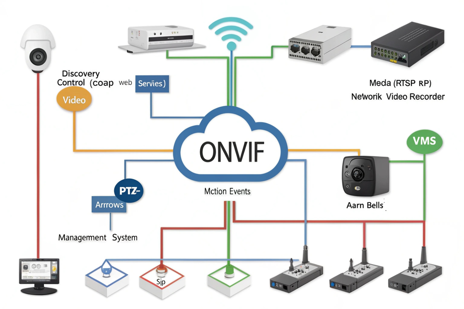
ONVIF (Open Network Video Interface Forum) 1 solves interoperability by splitting the job into two parts. The first part is device control. A client (NVR/VMS/intercom) talks to the camera using web-service style APIs (often SOAP/XML web services 2 over HTTP or HTTPS). These calls handle login, capabilities, profiles, encoder settings, PTZ commands, and event subscriptions. The second part is media streaming. Most ONVIF systems still deliver live video using RTSP and then RTP packets for the actual stream. This split matters in troubleshooting. A site can have perfect ONVIF control but blocked RTSP streaming protocol ports 3, so the camera appears online but shows a black screen.
Profiles are promises, not “everything works”
ONVIF Profiles 4 are feature bundles. A profile does not mean every camera function becomes universal. It means a camera and a client agree on a baseline set of services and behaviors. This is why one VMS can show video from any brand, yet advanced analytics or a vendor-specific HDR mode still needs the vendor app.
Discovery usually stays inside one VLAN
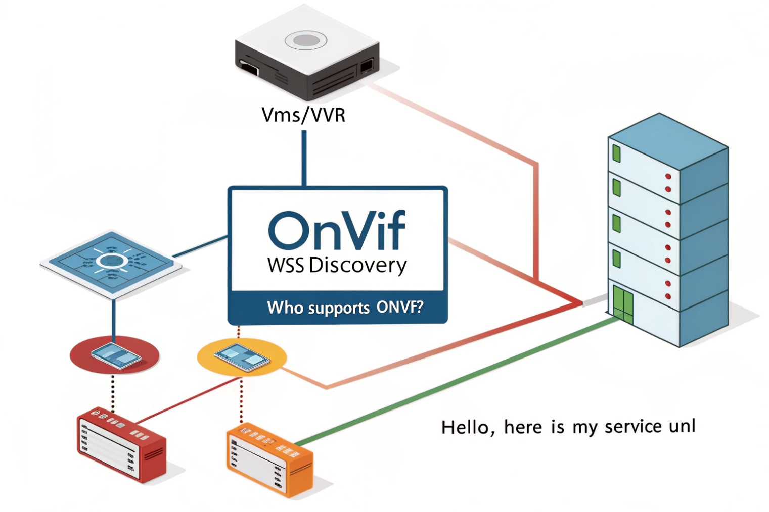
Most discovery uses WS-Discovery multicast 5 on the local network segment. It is fast, but it is not designed to cross routers by default. This is why discovery often fails between VLANs, even when the stream works fine by direct IP.
The simplest mental model
A practical model helps during integration:
1) The client discovers the device (or you add it by IP).
2) The client authenticates and reads capabilities.
3) The client selects a media profile and gets the RTSP URL.
4) The client starts the stream and optionally subscribes to events.
| ONVIF layer | What it does | Typical protocol | Common failure |
|---|---|---|---|
| Discovery | Finds devices on LAN | WS-Discovery multicast | Fails across VLANs |
| Control | Reads/sets camera features | HTTP/HTTPS web services | Auth mismatch or timeouts |
| Media | Carries video/audio | RTSP + RTP (Real-time Transport Protocol) media packets 6 | Port blocks, codec mismatch |
| Events | Sends motion/I/O alarms | Event service subscriptions | No events due to filters or time drift |
If this flow feels clear, the rest of ONVIF becomes easier. The next sections focus on the specific questions that decide real project success.
When teams treat ONVIF like “one checkbox,” projects become fragile. When teams treat ONVIF like a set of services with clear dependencies, projects become predictable.
Which ONVIF profiles (S, T, G, M) do my cameras support?
A spec sheet can claim “ONVIF compliant,” but the client still cannot control PTZ or pull H.265. That gap usually comes from profile assumptions.
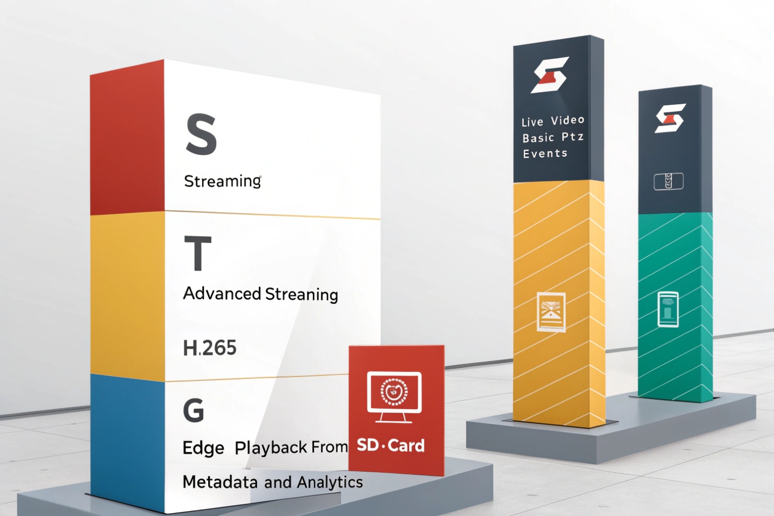
Profile S targets basic IP video streaming and PTZ control, Profile T adds modern video features like H.264/H.265 and better imaging controls, Profile G focuses on recording and playback to storage, and Profile M focuses on metadata and analytics events. Your camera only guarantees what its supported profiles require.
What each profile is meant to guarantee
Profile S: the common baseline for live viewing
Profile S covers core video streaming and many PTZ basics. Many NVRs use Profile S to get a stable stream and basic controls. It is the profile most people meet first, so it is also the one most people overestimate.
Profile T: the modern streaming profile
Profile T is often used for newer codecs and improved video configuration. Many modern cameras support it, but some older NVRs still behave like Profile S clients. When a camera offers H.265 but a client cannot decode it, the camera may still be “ONVIF,” yet the system still fails.
Profile G: recorded video access
Profile G is for devices that handle recording and playback functions in a more standardized way. Many projects still record by pulling RTSP into an NVR, so Profile G may not be required for basic recording workflows. Still, it can matter in systems that want standardized recording control.
Profile M: metadata and analytics
Profile M focuses on metadata streams and analytics events. It helps when the system needs events like people counting, line crossing, or richer scene metadata. The value depends on what the VMS can ingest and how the camera exposes analytics.
How to confirm profile support with evidence
A clean process avoids guessing:
- Check the camera’s ONVIF page in its web UI. Many vendors list supported profiles.
- Use an ONVIF test tool to read GetCapabilities and profile tokens.
- Confirm the client supports the same profile level. A camera can support Profile T, while the NVR acts like Profile S.
| Profile | Main goal | Typical use | What to verify first |
|---|---|---|---|
| S | Live streaming + basic PTZ | Viewing, simple recording | RTSP stream + auth |
| T | Modern streaming + imaging control | H.265 projects, better control | Codec support end-to-end |
| G | Recording + playback services | Standardized storage access | Playback API support in VMS |
| M | Metadata + analytics | Event-driven automation | Event subscription + metadata parsing |
A project stays stable when the profile match is proven in a test bench before installation. This matters even more when SIP intercoms or indoor stations pull camera video, because those devices often support a limited subset.
How do I add ONVIF cameras to NVRs, VMS, and SIP intercoms?
Integrations often fail because teams add cameras three different ways on three different platforms. Each path has different requirements and different pitfalls.
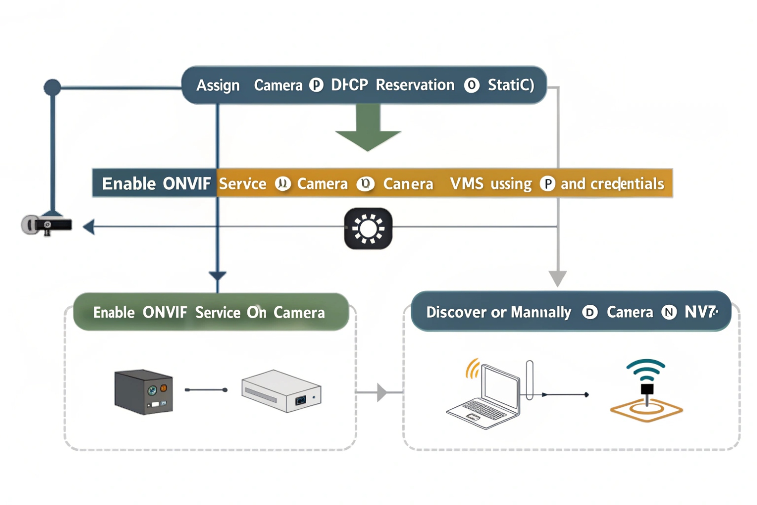
Most systems add ONVIF cameras by discovering them, entering credentials, then selecting a media profile that maps to a stream and encoder settings. VMS/NVR platforms often use full ONVIF control, while SIP intercoms and indoor stations sometimes only use ONVIF for discovery and then pull RTSP for live preview.
NVR and VMS onboarding workflow
A common, reliable workflow looks like this:
1) Put the camera and recorder on the same VLAN (at least during onboarding).
2) Use discovery, then log in with an ONVIF user.
3) Let the VMS read capabilities and create stream profiles.
4) Pick mainstream for recording and substream for multi-view, if the camera provides dual stream.
5) Set recording mode and event subscriptions.
The key is credentials. Many cameras separate “web admin” users from “ONVIF users.” Some vendors require enabling ONVIF and creating a dedicated ONVIF account. A lot of “ONVIF failed” errors are simply wrong user scope.
SIP intercom and indoor station use cases
In many SIP intercom deployments, an indoor station or an IP PBX client wants a door video preview. That integration often follows one of these patterns:
- The indoor station discovers the camera via ONVIF, then pulls the RTSP URL.
- The indoor station skips discovery and uses a pre-built RTSP URL directly.
- The intercom itself exposes an ONVIF device interface, so a VMS can add the intercom as a camera.
A practical approach is to keep the video path simple. Use ONVIF for discovery and credential handling when it is supported, then confirm the RTSP stream works with the chosen codec.
A clean “compatibility-first” configuration
For broad interoperability:
- Use H.264 on the substream for maximum decoder compatibility.
- Use H.265 only when every client in the chain supports it.
- Keep audio consistent. Many recorders ignore audio unless it is enabled in the selected profile.
| Platform type | Best add method | What it needs | Common pitfall |
|---|---|---|---|
| NVR | ONVIF add + auto profile | ONVIF user + IP reachability | Wrong ONVIF account |
| VMS | ONVIF add + event mapping | Events + time sync | Events missing due to filters |
| SIP indoor station | ONVIF discovery or RTSP URL | RTSP reachable + codec decode | H.265 not supported |
| SIP intercom as camera | ONVIF profile + RTSP | Proper profile token | Stream token mismatch |
A short bench test saves hours later. One laptop on the same switch, one ONVIF tool, and one RTSP player can prove the full chain before installers touch ceilings and ladders.
Why does ONVIF discovery fail and how do I fix it?
Discovery failures feel like “the camera is dead.” In reality, discovery is a local multicast feature with strict network assumptions. One wrong VLAN design can break discovery across an entire campus.
ONVIF discovery often fails because WS-Discovery multicast does not cross VLANs, because firewalls block multicast/UDP, because cameras are on a different subnet, or because the client uses the wrong network interface. The fastest fix is to test discovery on the same L2 segment, then fall back to manual add by IP and open only the needed ports.
The most common root causes
VLAN and routing boundaries
WS-Discovery is usually local only. When cameras sit in a security VLAN and the VMS sits in a server VLAN, discovery can fail even when RTSP is reachable. This is normal behavior.
Multicast filtering and Wi-Fi isolation
Some switches and access points filter multicast or isolate clients. Guest Wi-Fi settings can block discovery. Some enterprise Wi-Fi setups require multicast optimization settings for discovery to work.
Host firewall and endpoint security software
A Windows firewall rule can block inbound discovery responses. Endpoint security suites can also block multicast and unknown service traffic.
Wrong NIC selection on multi-homed servers
A VMS server can have multiple NICs. A discovery tool can listen on the wrong one. This creates the illusion that nothing exists on the network.
A practical fix ladder
Start with the simplest step and climb only when needed:
1) Put a laptop on the same switch as the camera and test discovery.
2) If discovery works locally, accept that the VLAN boundary blocks discovery.
3) Add cameras by IP manually on the VMS/NVR.
4) Open required ports between VLANs for control and RTSP.
5) Use a discovery proxy only when operations demand centralized discovery.
Ports and traffic that usually matter
Many ONVIF control calls use HTTP/HTTPS ports (often 80/443 or vendor custom ports). Media often uses RTSP on 554. Discovery uses WS-Discovery multicast on UDP. A strict firewall can allow unicast control and RTSP while still blocking discovery. That is often the right security posture.
| Symptom | Likely cause | Quick test | Fix |
|---|---|---|---|
| No devices found, but ping works | VLAN boundary | Test on same switch | Manual add by IP |
| Some devices found, others missing | Multicast filtered | Capture traffic | Fix multicast policy |
| Discovery works on laptop, not on VMS | Wrong NIC or firewall | Bind tool to correct NIC | Allow discovery traffic |
| ONVIF add works, no video | RTSP blocked | Try RTSP player | Open RTSP and RTP ports |
A stable design does not depend on discovery across the whole enterprise. A stable design uses discovery only for commissioning, then uses inventory and fixed IP planning for operations.
What ONVIF settings affect resolution, bitrate, PTZ, and event alarms?
Many projects show video, yet the video looks blurry, uses too much bandwidth, or never triggers alarms. These issues often sit in encoder profiles and event mapping, not in the ONVIF checkbox.
Resolution, bitrate, and FPS come from the camera’s encoder configuration tied to an ONVIF media profile. PTZ depends on the PTZ configuration and permissions. Event alarms depend on subscriptions, correct event topics, and clean time sync, since many VMS rules rely on timestamps.
Media settings that control stream quality
ONVIF Media services expose encoder settings. The most important knobs are:
- Resolution (stream size)
- Frame rate (FPS)
- Bitrate mode (CBR or VBR)
- Max bitrate
- GOV length / I-frame interval
A VMS often creates two streams:
- Mainstream for recording and playback detail
- Substream for multi-camera grid preview
This dual stream approach reduces CPU load and bandwidth while keeping recorded quality high.
PTZ settings that decide whether control works
PTZ success depends on:
- Camera PTZ capability and ONVIF PTZ service support
- Profile token selection
- User permissions that allow PTZ commands
- Preset support and speed limits
If a camera supports PTZ but a VMS cannot move it, the cause is often wrong profile token selection or a user role that can view video but cannot control PTZ.
Event settings that decide whether alarms arrive
ONVIF events can include:
- Motion detection
- Digital input changes
- Tamper alarms
- Analytics events, if the camera exposes them
Event alarms require:
- The camera to publish the event topic
- The client to subscribe correctly (pull-point or notify methods)
- Time sync to be stable, since event correlation uses timestamps
- Correct VMS mapping from topics to alarms
A practical “quality and alarms” checklist
- Keep mainstream bitrate high enough for details, but do not exceed uplink limits.
- Keep substream small and stable for preview.
- Align codec choice with client decoders.
- Enable events in the camera and confirm the VMS sees them.
- Use Network Time Protocol (NTP) 7 for time sync across cameras and servers.
| Setting | Impacts | Recommended habit | Common mistake |
|---|---|---|---|
| Resolution/FPS | Detail and motion clarity | Match to scene needs | Max everything, then storage explodes |
| Bitrate mode | Bandwidth stability | Use CBR for strict links | VBR spikes cause packet drops |
| I-frame interval | Seeking and motion artifacts | Keep it consistent | Too long causes blocky motion |
| PTZ presets | Operator workflow | Define named presets | No presets, slow manual control |
| Event topics | Alarm automation | Test each topic | Assuming “motion” always maps |
In SIP intercom deployments, these settings matter for user experience. A door preview must load fast. A substream often works best for preview tiles, while the mainstream is better for recording and incident review.
Conclusion
ONVIF is the interoperability layer for discovery, control, streaming, and events. Profile matching, VLAN-aware design, and clean encoder/event settings create stable video across NVRs, VMS, and SIP intercom ecosystems.
Footnotes
-
Official ONVIF home for specs, conformance, and interoperability resources. ↩ ↩
-
Explains SOAP messaging basics used by many ONVIF control APIs. ↩ ↩
-
RTSP standard reference for common live stream setup and control behavior. ↩ ↩
-
Official ONVIF profile overview to verify what Profile S/T/G/M promise. ↩ ↩
-
WS-Discovery spec showing how local multicast discovery is designed to work. ↩ ↩
-
RTP standard reference for real-time media packet transport basics. ↩ ↩
-
NTP standard for time synchronization that improves event timestamps and correlation. ↩ ↩


