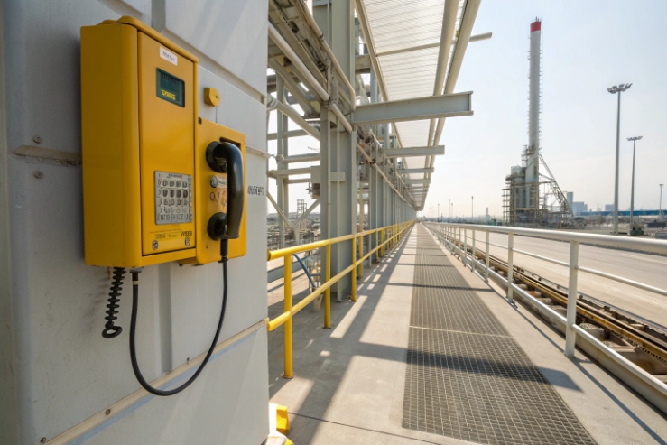
Downtime in hazardous areas is expensive. A dead phone can also become a safety incident. Power design is where many “certified” installs fail in the field.
Yes, many explosion-proof telephones support PoE. The right PoE type depends on your feature load, temperature class margin, and whether the circuit must be intrinsically safe or only installed in an Ex d/e system.

PoE on Ex telephones is a power-and-temperature contract
PoE is common, but the power class is the real question
Most Ex SIP telephones use Ethernet for signaling, so PoE is a natural choice. PoE simplifies installation, reduces power wiring, and makes UPS-backed uptime easier. The key detail is not “PoE yes/no.” It is “how much power is guaranteed at the device, and what happens at temperature extremes.”
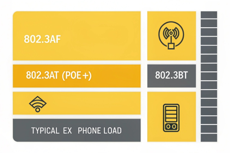
IEEE PoE budgets are usually discussed in two numbers: what the switch (PSE) can provide and what the device (PD) can count on at the far end. Type 1 (IEEE 802.3af Power over Ethernet (PoE) 1) supports up to 15.4 W at the PSE and about 12.95 W at the PD. Type 2 (IEEE 802.3at PoE+ (Type 2) via MDI Enhancements 2) supports up to 30 W at the PSE and about 25.5 W at the PD. Newer IEEE 802.3bt (Types 3/4) higher-power PoE 3 types go higher for very power-hungry loads.
Ex reality: more power means more heat
In hazardous areas, heat is part of compliance. Extra PoE watts become heat inside the enclosure. That impacts:
- maximum ambient rating
- speaker duty cycle at high temperature
- heater feasibility in low temperature
- long-term gasket life
So the best tender language ties power to function and ambient. It also asks for a thermal derating statement.
A simple power planning table that keeps everyone aligned
| Feature load on the phone | Typical PoE need | Why |
|---|---|---|
| Basic SIP calling + LEDs | 802.3af is often enough | Low steady power |
| Beacon + loud ringer + relays used | 802.3af or 802.3at | Peaks can rise |
| Camera module or strong beacon duty cycle | 802.3at preferred | More steady load margin |
| Heater for sub-zero starts | 802.3at or 802.3bt, or add DC | Heater is the big watt driver |
When this is clear, selecting the correct PoE standard becomes straightforward. Next, let’s pin down which PoE standards are normally supported and how to budget them for heaters, beacons, and relays.
Some buyers only ask for “PoE+.” The safer approach is to demand a defined class and an operating duty cycle.
Which PoE standards are supported—IEEE 802.3af/at/bt, power class, and budget for heaters, beacons, and relays?
If the project under-budgets PoE, the phone will still boot, then it will reset when the beacon and speaker run together. That looks like a network issue, but it is a power issue.
Use 802.3af for basic Ex SIP telephones, 802.3at for phones with higher accessory loads, and consider 802.3bt only if the phone truly needs high continuous watts (often for heaters). Always specify the PD budget at the phone, not only the PSE nameplate.
PoE budgets in plain numbers
- 802.3af (Type 1) is commonly referenced as 15.4 W at the PSE and ~12.95 W at the PD.
- 802.3at (Type 2 / PoE+) is commonly referenced as 30 W at the PSE and ~25.5 W at the PD.
- 802.3bt (Types 3/4) supports higher delivered power (commonly shown as ~51 W and ~71.3 W at the PD for Type 3/4 in many summaries).
Budgeting heaters, beacons, and relays without guesswork
A heater is not like a relay coil. It can dominate the whole budget. A beacon can be small, but strobe patterns can create peaks. Relays are usually low power, but external loads do not run from the phone’s PoE unless the phone is designed for it.
The clean way to spec is:
- define a worst-case mode (speaker max duty, beacon on, relays energized, camera on if present)
- define ambient extremes (hot day and cold day)
- ask the supplier to state maximum continuous PoE input needed for that mode
A tender-ready PoE budget table format
| Subsystem | Continuous W | Peak W | Duty cycle assumption |
|---|---|---|---|
| SIP core + Ethernet | ___ | ___ | always on |
| Audio amplifier | ___ | ___ | ___% |
| Beacon/strobe | ___ | ___ | ___% |
| Relays + I/O | ___ | ___ | worst-case energized |
| Heater (if used) | ___ | ___ | thermostat controlled |
In my product discussions at DJSlink, this table prevents most power disputes. It also forces the supplier to prove that the phone stays stable when fully loaded, not only when idle.
Now comes the hard safety question: is PoE+ “safe” in hazardous areas, and when do you need intrinsic safety barriers.
Is PoE+ safe in hazardous areas—temperature rise, intrinsically safe barriers, and ATEX/IECEx considerations?
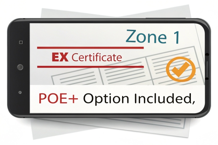
People often mix two ideas: “safe to use in Zone 1” and “intrinsically safe.” They are not the same. That confusion causes bad designs.
PoE+ can be used with Ex d or Ex e telephones if the device is certified for the hazardous area and the input power does not push surface temperatures beyond its temperature class. PoE+ is not automatically intrinsically safe. If the circuit must be Ex i (live work in Zone 0/1), you need an intrinsically safe Ethernet/PoE concept (PoEx) using certified barriers or switches.
“Explosion-proof phone” does not mean “intrinsically safe circuit”
- Ex d (flameproof) contains an internal ignition and stops flame transmission through certified joints.
- Ex e (increased safety) avoids arcs and hot spots through robust design and controlled terminations.
- Ex i (intrinsic safety) limits energy so ignition is prevented, and it supports live connection and disconnection in certain zones.
Standard PoE and PoE+ can carry enough energy that they are not treated as intrinsically safe by default. Intrinsic safety needs a deliberate limitation method, typically aligned to IEC 60079-11 intrinsically safe apparatus requirements 4.
Temperature rise is the main PoE risk inside Ex d/e equipment
PoE power becomes heat. In ATEX/IECEx terms, the phone’s certificate is tied to:
- maximum ambient range
- permitted input power
- temperature class marking
- any special conditions of use
So the safe way to spec PoE+ is to require the supplier to confirm:
- the PoE mode used (af/at/bt)
- maximum PD power draw at worst-case features
- operation at maximum ambient without exceeding its certified temperature limits
A simple decision table for buyers
| Your site need | Typical Ex approach | What to specify |
|---|---|---|
| Normal operation, no live work on energized ports in zone | Ex d or Ex e phone with PoE | Confirm certificate + max PoE draw |
| Live plug/unplug in zone, strict energy limitation | Ex i Ethernet/PoE concept (PoEx) | Use certified IS barriers/switches |
| Heater needed in Zone 1 | Ex d/e phone + higher power budget | Thermal derating and duty-cycle limits |
This is the point to keep simple with clients: PoE is fine when it matches the certified product design and the installation rules. Intrinsic safety is a different design path and needs the right barrier equipment.
Next, let’s talk about network power architecture, because uptime is usually a switch room problem, not a handset problem.
How should network power be designed—PSE switches, injectors, surge protection, and redundant 24 V fallback?
A phone can be perfect, but if the switch drops power during storms, the phone is still down. Harsh sites need layered power design.
Use managed PoE switches (PSE) with a real power budget, back them with UPS, add surge protection at boundaries, and use a defined fallback path only when it is certified and practical for the Ex type.
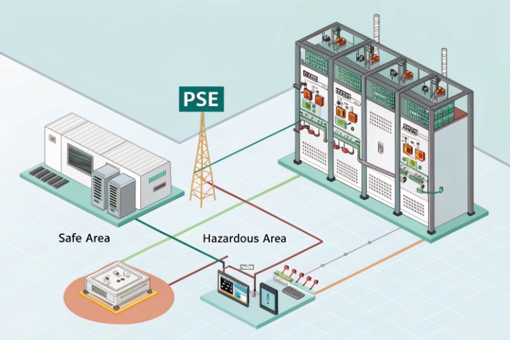
PSE switches vs injectors
- PoE switches are cleaner for multi-phone sites. They let you monitor port power, reboot ports, and manage budgets.
- Injectors are fine for one-off installs, but they are harder to supervise and they often get placed in poor environments.
For critical sites, managed PSE is worth it. It also supports power negotiation features on many networks.
Surge protection: protect the switch and the phone
SIP phones in offshore, mining, and chemical plants are exposed to lightning coupling through long tray runs. Surge protection should be layered:
- at building or cabinet entry
- near the equipment when the run is long
- with bonding kept short and low impedance
When writing immunity and coordination language, anchor it to the IEC 61000-4-5 surge immunity test method 5.
Redundant 24 V fallback: useful, but only when it fits the certification and maintenance model
Some projects want PoE as primary and 24 V DC as backup. This can work, but it adds complexity:
- extra cable entry and glands
- extra heat load
- extra points of failure
- and a need to confirm certification conditions still apply
In many Ex deployments, the best “redundancy” is UPS-backed network power at the switch plus a redundant network path. That keeps the phone wiring simple and avoids mixed-power confusion.
A practical “uptime” design checklist
| Item | Recommended approach | Why |
|---|---|---|
| PoE budget | 30–50% headroom on PSE | Avoid brownouts |
| UPS | Back up PSE and upstream network | Keeps SIP registration alive |
| Surge | PoE/data SPDs at boundaries | Stops port damage |
| Monitoring | SNMP alerts for PoE port status | Faster recovery |
| Field spares | Spare glands/SPDs and a spare phone | Cuts downtime |
This is also where installation discipline matters. A perfect design can fail if grounding and shield termination are sloppy. Next section covers cabling rules and how to go beyond 100 m correctly.
What cabling and distance rules apply—Cat5e/Cat6, 100 m limit, PoE extenders, and outdoor UV/chemical-resistant cables?
Long runs are where PoE becomes fragile. Voltage drops, resistance rises, and surge coupling increases. Cable choice becomes a reliability decision, not a cost detail.
Use Cat5e or Cat6 structured cabling with the standard 100 m channel limit as your baseline. For longer distances, use intermediate switches, PoE extenders, or convert to fiber and inject PoE near the device. In hazardous areas, select cables and installation methods that match IEC/EN 60079-14 or NEC hazardous-location practices, and use UV/chemical-resistant outdoor jackets.
The 100 m rule still matters
The 100 m baseline is rooted in structured cabling design rules; when you need a formal reference point for channel expectations (including power delivery considerations), cite ISO/IEC 11801-1 generic cabling for customer premises 6. When PoE is added, the cable also carries DC current, so voltage drop becomes the limiter before data fails.
Choosing Cat5e vs Cat6 for PoE in harsh sites
- Cat5e is often enough for 802.3af/at in short-to-medium runs.
- Cat6/Cat6A can help with margin, especially if the conductor is larger and the environment is noisy.
- Shielded cable can help in EMI-heavy plants, but only if the shield is terminated correctly.
How to go beyond 100 m without breaking the system
- Add an intermediate PoE switch in a cabinet (often the cleanest).
- Use PoE extenders at defined points, preferably in controlled enclosures.
- Use fiber for the long backbone, then place a PoE switch near the phone.
Fiber is often the best solution offshore and in mines because it reduces surge coupling and removes long copper exposure. Then PoE is only used on the short last segment.
Outdoor jacket and chemical resistance are not optional
For offshore, chemical, and mining sites, the cable must survive:
- UV exposure
- oils and greases
- chemical mist
- temperature swings
- mechanical abrasion in trays and conduits
So the tender should specify jacket properties and approvals, not only “Cat6.” This is also where regional code matters (IEC/EN vs NEC). A hazardous-location cable selection approach under NEC can look different than IEC-style practice, so the project must state which rule set governs.
If your project is Zone-based, tie the “how it’s installed” portion of the requirement to the current IEC 60079-14 electrical installation standard for explosive atmospheres 7 so cable, entries, and inspection assumptions stay consistent.
A cabling spec table that buyers can paste into tenders
| Cable item | Minimum ask | Harsh-site upgrade |
|---|---|---|
| Category | Cat5e or Cat6 | Cat6A industrial |
| Jacket | UV-resistant outdoor | Oil/chemical resistant, low smoke where needed |
| Shielding | As required by EMI study | STP with 360° termination plan |
| Distance | 100 m channel baseline | Fiber backbone + PoE at edge |
| Hazardous area alignment | Install per site code | Use cable/accessory kits aligned to IEC/EN 60079-14 |
This section is where most uptime is won. Good cable and topology reduce both power drop and surge exposure.
Conclusion
Explosion-proof telephones can support PoE, but the right PoE type depends on feature load, thermal limits, and whether you need Ex d/e or true Ex i (PoEx) power architecture.
Footnotes
-
Official IEEE page describing PoE Type 1 power via MDI parameters used for af budgeting. ↩︎ ↩
-
IEEE amendment introducing PoE+ higher power and classification—useful for specifying Type 2 requirements. ↩︎ ↩
-
IEEE 4-pair PoE standard for higher-power devices and planning Types 3/4 budgets. ↩︎ ↩
-
Defines intrinsic safety energy limits—useful when your project requires Ex i Ethernet/PoE concepts. ↩︎ ↩
-
Surge immunity test method reference to align device immunity claims and SPD coordination language. ↩︎ ↩
-
Structured cabling standard underpinning 100 m channel design and supporting power delivery over balanced copper links. ↩︎ ↩
-
Core installation standard for Ex equipment selection and erection, including cable routing, glands, and inspection basics. ↩︎ ↩


