Paging sounds weak, then someone turns every knob to maximum. The next day the audio clips, hum appears, and the intercom gets blamed.
A line output is a fixed-level, low-impedance analog signal designed to feed a line input on mixers, amplifiers, or paging systems. It follows a predictable signal path and standard voltage references, so good wiring and gain staging keep speech clear and loud.

How a line output audio interface works inside real systems
What “line out” is built to do
A line output is the clean hand-off point between devices. It is meant to send audio to a destination that already has its own gain control. Think of it as a “send” signal, not a “power” signal. The destination might be a mixer channel, a DSP input, a paging amplifier line input, or a recording interface input.
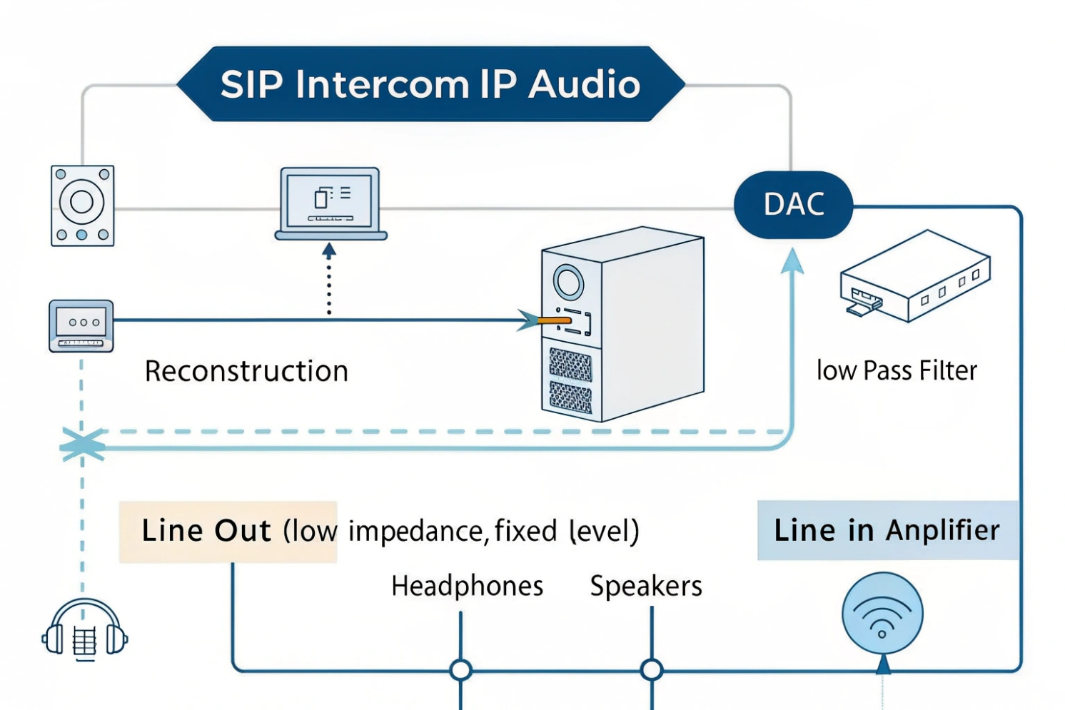
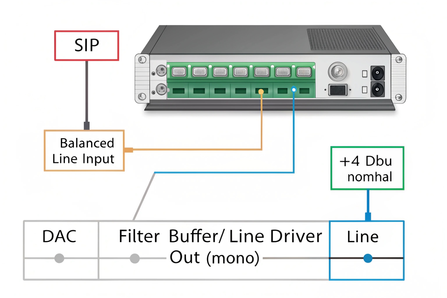
Inside the device, the audio path is usually:
1) Digital audio stream
2) DAC (digital-to-analog conversion) 1
3) Reconstruction filter (smooths the analog waveform)
4) Buffer / line driver (low output impedance, stable voltage)
That last stage matters. A typical line output has low output impedance 2, often in the tens to a few hundred ohms. The receiving line input is high impedance, often 10 kΩ or higher. This pairing keeps the voltage level stable. It also reduces distortion.
Line outputs are often stereo. That means two separate mono channels: Left and Right. Multichannel gear simply exposes more line outputs for routing and zones.
What line out is not
Line out is not a headphone amp. It is not a speaker amp. If headphones or passive speakers are connected directly, the level can be very low. Distortion can appear. In worst cases, the output stage can overheat or fail. This is why paging installs should never attempt to drive 70V/100V speaker lines from a line output. The correct chain is always line out → amplifier → speakers.
A quick “know it in 10 seconds” table
| Output type | Designed load | Typical use | Common mistake |
|---|---|---|---|
| Line out | ≥10 kΩ | Feed a line input | Plugged into a mic input, clips |
| Headphone out | 16–300 Ω | Drive headphones | Overdrives line input, noisy |
| Speaker out | 4–8 Ω | Drive passive speakers | Can damage line input gear |
A short lesson from a past site: an installer fed a SIP intercom line out into a paging amp MIC input because it “was the only free port.” The audio sounded loud but harsh. The fix was simple: move to LINE input and reset gain. The clarity improved immediately, and the volume needed dropped.
Now that the purpose is clear, the next step is understanding the level categories that cause most wiring errors.
A correct level match saves hours of troubleshooting later.
What’s the difference between mic level, instrument level, and line level?
People often say “audio is audio.” In paging and VoIP integrations, that belief causes distortion, hiss, and weak announcements.
Mic level is very low and needs a preamp. Instrument level is higher but needs a high-impedance input. Line level is a standardized, stronger signal used between devices, usually −10 dBV (consumer) or +4 dBu (pro).
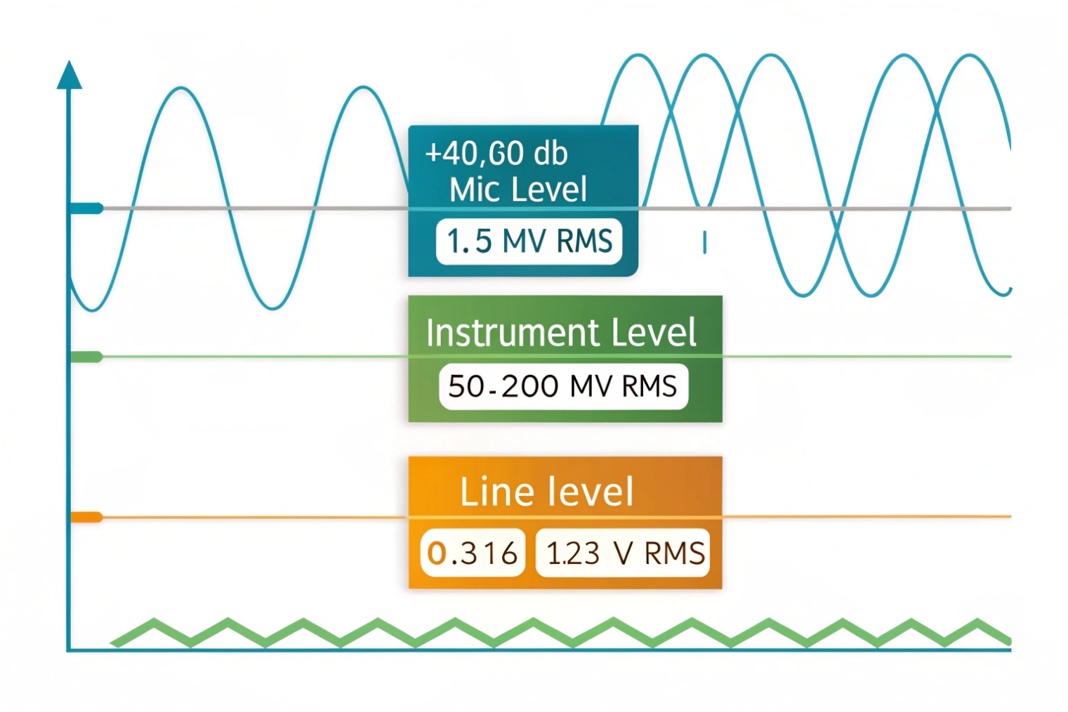
Mic level: tiny voltage, big gain
Mic level sits at the bottom. Speech into a microphone can be only millivolts. That is why mic inputs include a preamp that adds large gain. This gain also amplifies noise. So a mic input is sensitive by design.
If a line output is plugged into a mic input, the mic preamp can clip even at low knob settings. The sound becomes sharp and brittle. It can also trigger automatic gain control behavior in some paging amps.
Instrument level: different because of impedance
Instrument level is common for guitars and pickups. The key issue is not only voltage. It is input impedance. Pickups often need 500 kΩ to 1 MΩ input impedance to avoid tone loss. A normal line input is far lower, often 10 kΩ to 50 kΩ. That mismatch dulls the sound.
Instrument level is less common in access and paging jobs, but it appears when sites connect legacy sources like radios or special alert devices.
Line level: predictable and stable
Line level sits above both. It is designed for device-to-device connections. Two nominal references are used in the industry:
- Pro audio: +4 dBu (nominal)
- Consumer audio: −10 dBV (nominal)
A line output is usually “fixed-level” or “near fixed-level.” Some devices allow selection between these references or provide a trim. The goal is consistent signal delivery and clean gain staging at the destination.
| Level type | Typical signal strength | Typical input type | What it feeds well |
|---|---|---|---|
| Mic level | Very low | Mic preamp | Mixers, paging amps (mic in) |
| Instrument level | Low to medium | Hi-Z input | DI boxes, instrument inputs |
| Line level | Medium to high | Line input | Amps, DSP, mixers (line in) |
If a SIP intercom provides line out, it should land on a line input. That single rule prevents most distortion cases.
Now that levels are clear, the next choice is wiring style. Long cable runs punish the wrong choice.
Should I use balanced or unbalanced line out for long cable runs?
Noise is the enemy of paging. Hum and buzz make speech hard to understand. Noise also triggers people to raise volume, which creates clipping.
Use balanced line out for long runs because it rejects common noise. Use unbalanced for short runs only. Balanced wiring is more stable near power cables, motors, and elevators.
Balanced: differential audio with noise rejection
Balanced audio wiring 3 uses two signal conductors plus a shield. The destination reads the difference between the two signal lines. Noise picked up along the run tends to appear on both lines. It cancels out at the input through common-mode rejection 4.
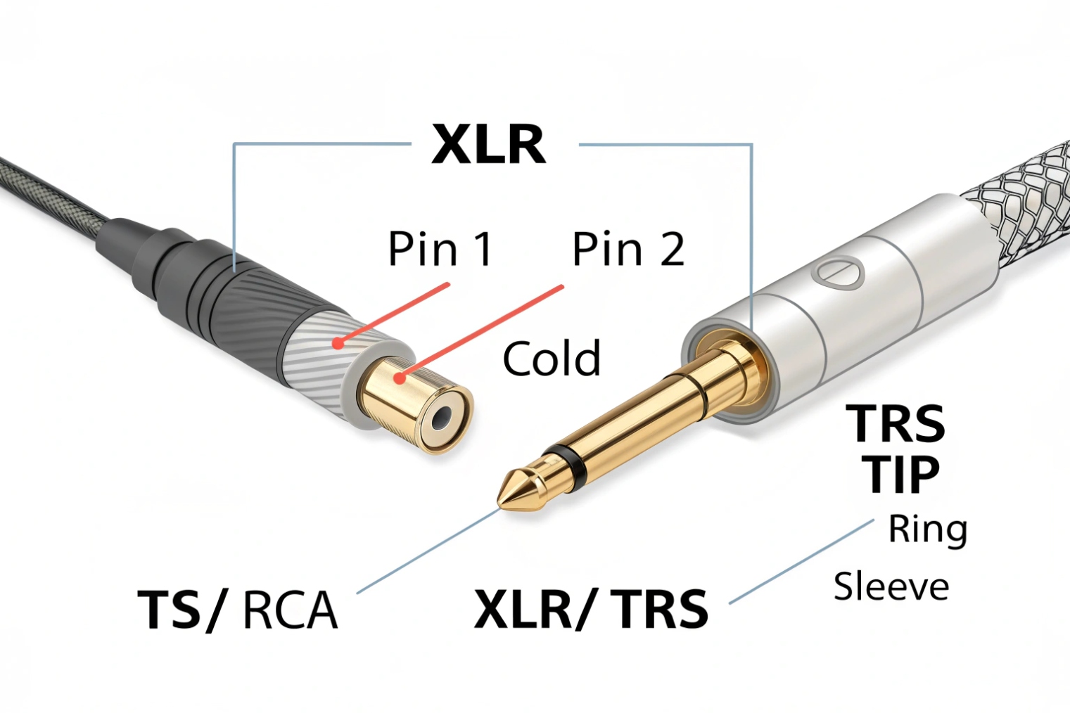
Common balanced connectors and pinouts:
- XLR: pin 2 hot, pin 3 cold, pin 1 shield
- TRS: tip hot, ring cold, sleeve shield
Balanced is the best default for:
- Long corridors
- Parking garages
- Industrial plants
- Elevator machine rooms
- Any rack-to-door or rack-to-building runs
Unbalanced: simple, but easy to pollute
Unbalanced audio uses one signal conductor and one shield/return. The shield is part of the circuit, so ground differences and interference become audio. This is why unbalanced can sound fine on a short desk run and terrible across a building.
Typical unbalanced connectors:
- RCA
- TS (mono 1/4")
Practical rules that work on site
Distance limits depend on cable quality and EMI, but simple rules help decisions:
- Unbalanced: keep it short, and avoid parallel runs with AC power
- Balanced: safe for longer runs and noisy environments
If the device only has unbalanced line out but the run must be long, a few fixes are reliable:
- Add a line isolation transformer to break ground loops
- Convert to balanced using a small interface near the source
- Place the amplifier closer and extend speaker lines instead, when design allows
| Option | Best when | Common symptom it fixes |
|---|---|---|
| Balanced TRS/XLR | Long runs | Hum, RF noise, buzz |
| Unbalanced RCA/TS | Short runs | Simple installs |
| Transformer isolator | Mixed grounds | Low-frequency hum |
| Unbalanced-to-balanced converter | Only unbalanced source | Noise on long runs |
For SIP intercom paging, balanced wiring often becomes the difference between “good enough” and “clean every day.”
Now the hardest part for many teams is level numbers. dBu and dBV look similar but they do not match.
How do dBu, dBV, and Vrms relate to line output levels?
Audio spec sheets look complicated, so installers guess. That guess shows up as “weak audio” or “always clipping.”
dBu and dBV are voltage measurements expressed in decibels. dBu references 0.775 Vrms, and dBV references 1.0 Vrms. Vrms is the real voltage. Converting them helps match pro (+4 dBu) and consumer (−10 dBV) gear.
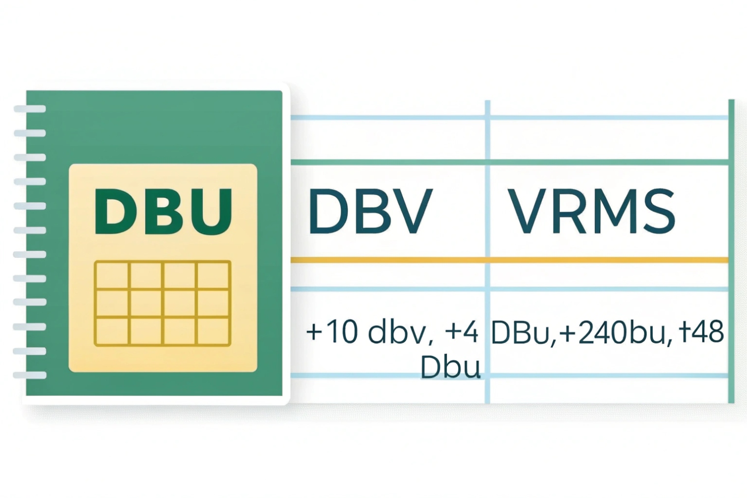
The reference points
- 0 dBu = 0.775 Vrms
- 0 dBV = 1.0 Vrms
That is the whole reason the same voltage can have different dB numbers in different units.
The useful conversions
These formulas stay consistent:
- Vrms from dBu: Vrms = 0.775 × 10^(dBu/20)
- Vrms from dBV: Vrms = 1.0 × 10^(dBV/20)
Two common nominal points:
- +4 dBu ≈ 1.23 Vrms
- −10 dBV ≈ 0.316 Vrms
This gap is large. It is about 12 dB. So feeding a consumer input with a hot pro output can clip the input stage. Feeding a pro input with a consumer output can sound weak and noisy if the destination gain is pushed too high.
Headroom matters as much as nominal
Nominal level is not the peak level. Speech has peaks. Paging tones have peaks. Many devices list maximum output level, like +18 dBu or +24 dBu. That max level is headroom. More headroom lets a system run at a strong nominal level while keeping peaks clean.
The best gain staging 5 habit is simple:
- Keep the source line out near its nominal setting
- Trim the destination input so it reaches the needed loudness
- Avoid “source at 5% and amp at 95%” because it raises hiss
- Avoid “source at 100% into consumer input” because it clips
| Unit | Reference | Common nominal | Typical gear |
|---|---|---|---|
| dBu | 0.775 Vrms | +4 dBu | Pro mixers, DSP, rack amps |
| dBV | 1.0 Vrms | −10 dBV | Consumer amps, simple inputs |
| Vrms | Actual voltage | 0.316 / 1.23 | Used in engineering specs |
With these numbers clear, connecting a SIP intercom to a paging amplifier becomes a repeatable workflow, not trial and error.
Now the real-world wiring and system design choices can be described clearly.
How do I connect line out from SIP intercoms to amplifiers or paging systems?
Paging systems fail when the connection is “technically working” but not engineered. The fix is usually correct inputs, correct cabling, and correct gain staging.
Connect SIP intercom line out to an amplifier’s LINE/AUX input, match the expected level reference, and use balanced wiring for long runs. For 70V/100V paging, always feed a paging amplifier or zone mixer first. Never connect line out directly to a speaker line.
Step 1: pick the right destination input
Most paging amplifiers offer:
- MIC inputs (high gain)
- LINE/AUX inputs (correct target for line out)
- Speaker outputs (70V/100V or low-Z speaker outputs)
A SIP intercom line out should go into LINE/AUX. If only MIC inputs exist, use a pad or an interface, but treat it as a workaround. A proper line input is the stable path.
Step 2: choose balanced when distance is real
If the intercom has balanced line output, use it for runs that leave the room. If only unbalanced output exists, keep the cable short. If the amplifier is far, convert to balanced near the intercom or use an isolation transformer to prevent hum.
A common building pattern is: intercom at entrance, paging rack in MDF. That run is often long and noisy. Balanced wiring reduces support calls.
Step 3: handle 70V/100V correctly
A 70V/100V distributed speaker system 6 is a distribution system. It needs a power amplifier that outputs high voltage. Line out is only a signal. So the chain should look like:
SIP intercom LINE OUT → mixer/DSP/zone controller LINE IN → paging amplifier → 70V/100V speaker line
If the site needs multiple paging zones, add a zone mixer or DSP in the middle. Do not split line out with random Y cables across long distances. Use proper line distribution if one source must feed many destinations.
Step 4: set gain staging like a checklist
A simple setup process keeps speech clean:
1) Set intercom output around nominal
2) Set amplifier input trim to desired loudness
3) Speak at real distance and real volume at the door
4) Verify no clipping indicators on the amp or DSP
5) Check for hum with the door closed and open, since ground loops change
If speech is weak, raise the amplifier input trim first. If clipping happens, lower the intercom output or apply a pad, then retune the amp.
Step 5: plan for monitoring and fail-safe
Some paging jobs need a local monitor speaker or recording feed. Use a line-level distribution amplifier or DSP output split. Keep impedance high on all destinations. This avoids level drop and distortion.
| Use case | Best connection | Key setting |
|---|---|---|
| Small door + local powered speaker | Line out → powered speaker line in | Match −10 dBV or +4 dBu |
| Door + rack paging amp far away | Balanced line out → balanced line in | Avoid parallel AC runs |
| Multi-zone paging | Line out → DSP/zone mixer → paging amp | Set per-zone trims |
| Existing PA mixer | Line out → mixer line channel | Use EQ for speech intelligibility |
| Noisy site (factory) | Balanced + isolation if needed | Kill hum before boosting volume |
In SIP intercom deployments, line out is often used for two reasons: local horns for alerts, and integration into existing paging racks. When the design respects line level, cable type, and gain staging, the result stays clean even after months of daily use.
Conclusion
Line out is a fixed, low-impedance signal for line inputs, not speakers. Match levels, use balanced for long runs, convert dBu/dBV correctly, and stage gain for clean paging.
Footnotes
-
Overview of DAC basics so you understand where analog line-level audio is created. ↩ ↩
-
Explains why low source impedance and high input impedance keep line-level voltage stable (bridging). ↩ ↩
-
Practical balanced vs unbalanced interconnect guidance used by installers and system designers. ↩ ↩
-
Defines CMRR and why balanced lines reject noise picked up along long cable runs. ↩ ↩
-
A clear checklist for gain staging to avoid clipping, hiss, and “turn every knob” failures. ↩ ↩
-
Explains constant-voltage 70V/100V speaker distribution and why it must be driven by an amplifier. ↩ ↩


