
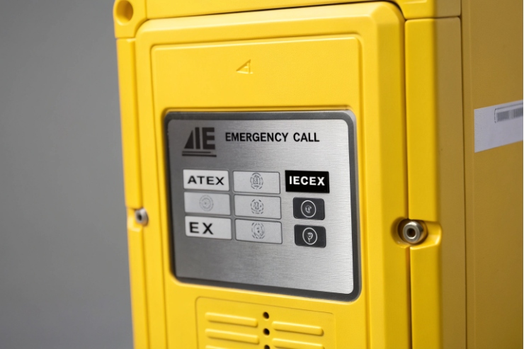
A certified Ex telephone can still fail an audit if the grounding is weak. One loose bond can turn a safe installation into a risk.
An explosion-proof telephone must be bonded into the site’s equipotential bonding system, with a correctly sized PE/bonding conductor, a reliable armor-to-enclosure bond where used, and test records that prove continuity and ongoing condition.

What “good grounding” looks like for Ex telephones in the real world?
Grounding for an explosion-proof telephone is not only about shock protection. In hazardous areas, bonding also helps prevent dangerous potential differences, limits static build-up, and keeps metalwork at the same potential during faults. The safest way to think about it is simple: the phone enclosure, glands, armor, mounting bracket, and any nearby metalwork should be at the same potential, and the bonding path should stay intact even after years of vibration, salt, and maintenance—by tying into the site’s equipotential bonding system 1.
In practical projects, grounding problems show up as:
- corrosion under a lug that slowly raises resistance,
- paint or powder coat left under a bonding washer,
- armor clamped but not bonded (so it floats),
- a reducer/adaptor stack that loosens over time,
- a “bond chain” where one removed connection breaks bonding for other items.
My baseline rule is: the grounding lug on the Ex telephone is not decoration. It is a functional part of the safety system, and it needs a defined conductor, route, termination method, and verification plan.
The three grounding paths you must separate in your specs
1) Protective earthing (PE) path: the fault-clearing path tied to the site earthing system.
2) Equipotential bonding path: keeps exposed metal parts at the same potential.
3) Cable shield/armor bonding: manages EMC and keeps armor from floating.
These three paths often meet at the same bonding bar, but they should not be mixed in drawings and tenders without clarity.
| Grounding item | Purpose | What “done right” means |
|---|---|---|
| External grounding lug | Primary bonding point on the enclosure | Direct bonding conductor, corrosion-protected joint |
| Cable armor termination | Keeps armor at earth potential | Armor clamped + bonded via earth tag/banjo or gland method |
| Cable shield continuity | EMI control for Ethernet/PoE noise | 360° shield bond where required, not a long drain wire loop |
| Verification | Proves it stays safe | Continuity tests + periodic inspection records |
If this foundation is clear, choosing the right standard path becomes easier, because every code system is trying to achieve the same outcomes.
The next step is deciding which standards actually govern bonding and earthing on your project.
Which standards define bonding and earthing—IEC 60079-14, NEC 501, and ATEX installation rules?
Hazardous area grounding rules change depending on where the project is built and which compliance model the owner uses. A phone can be IECEx/ATEX certified, but the site may still be under NEC or local electrical rules. That is why the tender must state the governing standard set up front.
In Zone 1/2 projects, IEC 60079-14 is the core installation standard for Ex equipment, and IEC 60079-17 drives inspection and maintenance. In Class/Division projects, NEC Article 501 applies for hazardous locations and points back to NEC Article 250 for grounding and bonding. In the EU, ATEX workplace duties come from Directive 1999/92/EC, and installation practice commonly aligns to EN/IEC 60079-14.
IEC path: Zone system (IECEx / ATEX technical practice)
For Zone 1/2 sites, the key installation standard is IEC 60079-14 2. It includes protective equipotential bonding requirements and guidance on how bonding connections should be arranged so a single removed connection does not break bonding for other parts. IEC 60079-17 3 then supports inspection and maintenance of hazardous area installations, and it supplements IEC 60364-6 verification concepts.
This matters for an Ex telephone because:
- the phone enclosure is an exposed conductive part,
- bonding must be secure against loosening,
- and the installation must follow the equipment instructions and the selected protection concept.
NEC path: Class/Division system (North America)
NEC Article 501 covers Class I hazardous (classified) locations. For grounding and bonding detail, the NEC relies heavily on NEC Article 250 grounding and bonding principles 4. In plain terms, NEC expects:
- non-current-carrying metal parts to be bonded,
- continuity of raceways and enclosures to be ensured,
- and approved bonding methods used even when a separate equipment grounding conductor is present.
For a C1D1/C1D2 telephone install, the “right” method may be conduit with listed fittings and seals, or it may be cable with listed connectors. Either way, bonding continuity is not optional.
ATEX workplace rules: EU duty-holder requirements
ATEX has two sides in daily work:
- product compliance (equipment directive) and
- workplace / user obligations (workplace directive).
Owners and employers must assess explosion risks and manage safe installation and maintenance, including duties set out in the ATEX Workplace Directive 1999/92/EC 5. In practice, EU site rules often reference EN 60079-14 for installation and EN 60079-17 for inspection.
| Region model | Installation core | Grounding/bonding anchor | What to put in your tender |
|---|---|---|---|
| IECEx / ATEX (Zone) | IEC/EN 60079-14 | Equipotential bonding + PE rules | “Install per IEC/EN 60079-14 and equipment instructions” |
| NEC (Class/Div) | NEC 501 | NEC 250 (bonding/grounding) | “Install per NEC 501 and Article 250 bonding rules” |
| Mixed global sites | Both kits | Two compliant BOMs | “IECEx kit and NEC kit must be offered separately” |
When the standard path is stated clearly, the PE conductor spec becomes a straightforward engineering decision instead of an argument during commissioning.
How should the PE conductor size, route, and termination be specified for Zone 1/2 areas?
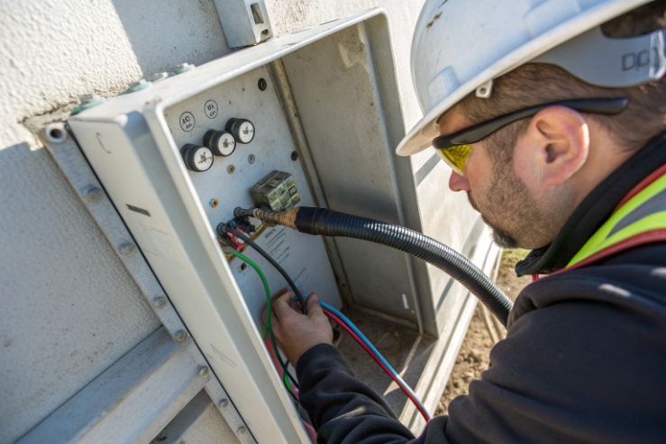
A common mistake is to write “provide earthing” without defining conductor size and joint quality. The bond then becomes a thin wire on a painted surface, and corrosion takes it from “works today” to “fails later.”
For Zone 1/2, specify a protective equipotential bonding conductor sized per the installation rules (often minimum cross-sections are defined), route it short and mechanically protected, and terminate it with a secure lug on a clean metal bonding point that is protected against corrosion.
Size: don’t guess, define which rule you are using
Two sizing ideas are usually involved:
- Minimum bonding conductor sizes for hazardous area bonding (often stated as minimum cross-sections for protective equipotential bonding conductors, with extra notes about mechanical strength).
- General PE sizing rules used across low-voltage installations (often based on phase conductor size or adiabatic calculation), commonly aligned with IEC 60364-5-54 protective conductors and bonding conductors 6.
For a weatherproof Ex telephone powered by PoE, the “supply conductor” is Ethernet pairs, but the enclosure still needs bonding. So the tender should specify an external bonding conductor size as a minimum and allow larger sizes when mechanical strength demands it.
A simple tender approach that avoids confusion:
- Define the minimum cross-section for the bonding conductor to the enclosure lug.
- State that the final size must also meet the site’s electrical installation standard and mechanical protection needs.
Route: short, protected, and not dependent on movable parts
A good routing method:
- Keep the bonding conductor as short as practical to the local equipotential bonding bar.
- Route it with mechanical protection (tray, conduit, protected path).
- Avoid routing that can be damaged during handset service or door opening.
- Do not use the phone mounting bolts as the only bonding method unless the manufacturer explicitly permits it and corrosion control is proven.
Termination: joint quality is everything
A strong termination includes:
- a correct ring lug or compression lug (tinned copper is common),
- a clean metal contact surface (remove paint only where needed),
- anti-loosening features (spring washer or approved locking method),
- torque to a stated value,
- corrosion protection after assembly (coating, grease, or joint compound suited for the site).
| Specification item | What to write | What it prevents |
|---|---|---|
| Minimum conductor size | “Bonding conductor minimum cross-section: ___ mm² Cu (or equivalent)” | Undersized, fragile bonds |
| Routing rule | “Shortest practical route to local bonding bar, mechanically protected” | Broken bonds during maintenance |
| Termination method | “Crimp lug, torque-controlled, protected against loosening and corrosion” | High-resistance joints |
| Identification | “Green/yellow marking and tagged at both ends” | Miswiring and missed inspections |
A simple personal reminder from field feedback: when a phone is mounted outdoors, the bonding joint must survive the same life as the enclosure. If the joint is not treated like an outdoor component, it will fail like one.
Now the question shifts to cable armor and earth tags, because many Ex telephone installs use armored cable in Zone 1/2.
Armor that is clamped but not bonded can float. In a fault or during static build-up, that creates dangerous potential differences. It also hurts EMC behavior for long cable runs.
Yes, when armored cable is used, the armor should be bonded as part of the equipotential bonding system. In practice, armor bonding is typically made at the gland using an earth tag/banjo (or a gland design that provides armor bonding), then linked to the enclosure’s bonding point or the site bonding bar per the equipment instructions.
What “bond the armor” means in a clean, auditable way
A common, audit-friendly method is:
1) Armor is clamped correctly in an armored Ex gland.
2) An earth tag/banjo is installed per the gland manufacturer instructions.
3) A short bonding strap connects the earth tag to the enclosure bonding point, or the bonding point connects directly into the local bonding bar.
The best arrangement avoids relying on a chain where removing one part breaks the rest. When several bonding conductors must connect at one point, a bonding rail or bar is cleaner and makes inspections faster.
When the external lug is the right place
Many Ex enclosures provide:
- an external grounding lug for equipotential bonding, and
- an internal earth terminal for protective conductors inside the box.
If the equipment instructions show the external lug as the primary bonding point, use it. If the armor is terminated inside the enclosure, ensure the internal earth terminal is also bonded to the same equipotential system. The key is that armor bonding must end up at the same potential reference as the enclosure.
Practical notes that reduce future corrosion failures
- If the lug is stainless and the conductor is copper, use correct lugs and corrosion control.
- Avoid stacking too many lugs on one stud. If more than two are needed, use a small bonding bar.
- After torque, mark the fastener with paint marker so loosening is visible during inspection.
- In coastal sites, treat the earth tag and bonding strap like external hardware. Use marine-grade materials.
| Armor bonding choice | When it fits | Risk if done poorly |
|---|---|---|
| Earth tag/banjo at gland + strap to lug | Most armored cable installs | Loose strap, corrosion under tag |
| 360° EMC gland bonding | When shield/EMC is critical | Wrong gland type breaks shield path |
| Internal armor termination | When enclosure design supports it | Harder inspection, more service errors |
Once armor bonding is defined, verification becomes the next big topic. Buyers often ask for “earth resistance,” but for equipment safety the more important checks are continuity and fault loop performance.
How are continuity, earth resistance, and insulation verified—megger tests, loop impedance, and periodic inspections?
A grounding requirement is only real if it can be measured, recorded, and rechecked. Without test records, the project depends on hope.
Verify the Ex telephone grounding with (1) continuity testing of the bonding path, (2) fault loop or bonding verification suitable for the earthing system, (3) careful insulation testing that does not damage electronics, and (4) periodic inspection schedules aligned with hazardous area maintenance standards.
Continuity: the basic proof of bonding
Continuity testing checks that the enclosure and bonding lug are actually connected to the equipotential system with low resistance. Good practice includes:
- use a low-resistance ohmmeter designed for bonding checks (typically aligned with IEC 61557-4 continuity and bonding measurement requirements 7),
- test from the enclosure lug to the nearest bonding bar,
- record the measured value, test method, and instrument ID.
The acceptance value is usually defined by the site standard rather than a single global number. The goal is a stable, low resistance bond that will carry fault current safely.
Earth resistance vs loop impedance: don’t mix them
- Earth resistance testing is often about the grounding electrode system (ground rods, grid). It is important for lightning and overall earthing design.
- Loop impedance (or fault loop performance) is what confirms the protective device will clear a fault fast enough in TN systems.
For Ex telephones, the key safety question is: if a fault occurs, will the fault current path be strong enough to trip protection quickly? That is why loop impedance or equivalent verification is often more useful than a single earth resistance number.
Insulation tests: protect electronics while testing the installation
A megger test can damage sensitive electronics if applied directly to Ethernet ports and internal circuits. A safer approach is:
- insulation-test the cable before connecting to the phone,
- or isolate/disconnect electronics as instructed by the manufacturer,
- use only approved test voltages and methods for the equipment type.
For PoE Ethernet, a cable certifier and link tests are often more appropriate than high-voltage insulation testing on connected ports.
Periodic inspections: keep it safe over years
Hazardous area installations require periodic inspection and maintenance. A good inspection checklist for Ex telephones includes:
- check lug tightness marks and visible corrosion,
- verify that no extra paint, sealant, or gasket blocks bonding surfaces,
- confirm gland and armor bonding is intact,
- confirm no unauthorized adaptors or stacked reducers have been added,
- re-test continuity on a schedule based on site risk.
| Verification item | When to do it | What to record |
|---|---|---|
| Bonding continuity | Commissioning + periodic inspections | Values, points tested, instrument ID |
| Loop/fault path check | Commissioning and after modifications | Results and protective device data |
| Insulation check | Before connecting electronics or per instructions | Method, voltage, pass/fail limits |
| Visual Ex inspection | Routine and periodic | Corrosion, looseness, damage, changes |
| Documentation review | Every inspection cycle | Match to drawings, certificates, method statements |
This verification plan also protects warranty. Many long-term failures come from small installation changes that were never recorded. A tight inspection and record routine stops that drift.
Conclusion
Ground the Ex telephone by bonding the enclosure, glands, and armor into the site equipotential system, then prove it with continuity and inspection records that match your governing code.
Footnotes
-
Practical overview of equipotential bonding goals and methods to reduce touch voltage and potential differences. ↩︎ ↩
-
IEC installation standard for selecting and installing Ex equipment, including bonding and earthing expectations. ↩︎ ↩
-
IEC inspection/maintenance standard that supports auditable periodic checks for hazardous-area electrical installations. ↩︎ ↩
-
NFPA explainer linking NEC Article 250 to grounding vs bonding fundamentals and fault-current return paths. ↩︎ ↩
-
Official EU workplace directive defining employer duties for explosion-risk control, documentation, and protective measures. ↩︎ ↩
-
Reference for PE/protective bonding conductor concepts and sizing approach used in low-voltage installations. ↩︎ ↩
-
Defines test instrument requirements for measuring resistance of protective earth and equipotential bonding conductors. ↩︎ ↩


