Lightning does not need to hit the phone to kill it. A nearby strike can travel through PoE, shields, and I/O, then the emergency point goes silent.
There is no single “correct” surge rating. The right requirement combines (1) equipment surge immunity targets, and (2) layered SPDs for power, PoE/data, and I/O that match the site lightning risk and the Ex installation method.

A practical way to specify surge protection for Ex telephones?
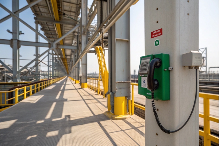
Surge protection for an explosion-proof telephone is a system design task. The phone is only one node. The surge enters from the outside world through three doors: the power source (AC/DC or PoE), the data path (Ethernet carrying SIP), and any field wiring (relay outputs, alarm inputs, beacon lines). The “surge rating” must cover all of them, or the weakest door will fail first.
A strong tender separates two things that are often mixed:
- Immunity target for the telephone: what surge levels the device should survive and still work.
- SPD requirements for the installation: what protection devices you install in panels and near the device so real surges do not reach the phone electronics.
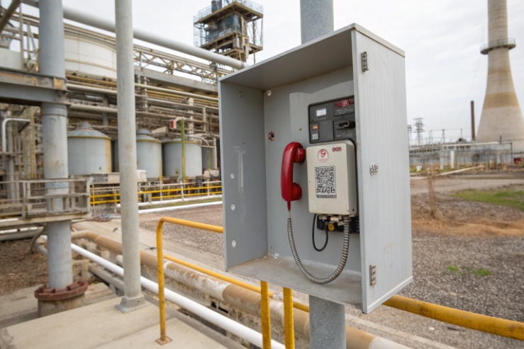
This also matters for Zone 1/2. A phone can be Ex d or Ex e, but a non-Ex SPD mounted in the wrong place can break compliance. So the clean approach is to keep high-energy SPDs in safe areas or in certified Ex enclosures, and keep device-level protection as a certified accessory or an external inline protector that does not touch flamepaths.
Step 1: Define the ports that need protection
- PoE / Ethernet (SIP traffic): common-mode surges are the main threat because they couple into shield, pairs, and enclosure.
- Relay I/O and alarm loops: long cables behave like antennas and bring in surge energy.
- Aux power (if not PoE): AC mains or DC feeders need Type 1/2/3 coordination.
Step 2: Pick the correct standards for each layer
- Equipment immunity is usually expressed with surge immunity test methods.
- SPD performance is expressed with SPD product standards for power and for signal networks.
- Rail sites often add railway EMC requirements for signalling/telecom equipment.
Step 3: Translate the site into a realistic target
A coastal platform, a mine with long outdoor runs, and a chemical plant with cable trays on steel structures do not behave the same. A practical tender uses “site classes” and maps them to protection layers and minimum ratings, instead of one big number.
A tender table that keeps suppliers aligned
| Item to specify | Minimum requirement | What it protects |
|---|---|---|
| Telephone surge immunity | Pass defined surge immunity levels on PoE/data and I/O while operating | Keeps the device alive |
| Power SPDs at panels | Type 1/2 at service/distribution when required by lightning exposure | Stops big energy early |
| Data/PoE SPDs | SPD designed for telecom/signalling networks, PoE pass-through, low insertion loss | Protects PHY and PoE PD |
| I/O SPDs | SPD matched to loop voltage and wiring type | Protects relays and inputs |
| Ex + IP integrity | No modifications to Ex d flamepaths; entry hardware maintains IP66/67 | Keeps compliance real |
| Grounding plan | Short, low-impedance bonding to a local bar | Makes SPDs work |
A simple rule used in many harsh projects: ask for immunity proof on the device, then use layered SPDs so the device never sees the full surge in the field.
This leads into the first real question: which surge standards should be written into your specs.
Which surge standards apply—IEC 61643-11, ITU-T K.21/K.45, IEC 61000-4-5, or EN 50121 for rail sites?
Many tenders list all standards at once. That creates confusion because these standards do different jobs.
Use IEC 61000-4-5 to define the phone’s surge immunity test method, use IEC 61643-11 for power SPDs, use IEC 61643-21 for data/telecom/PoE SPDs, and use ITU-T K.21/K.45 when you want telecom-style surge resistibility evidence for Ethernet/telecom ports. For rail sites, add EN 50121-4 to match railway signalling/telecom EMC expectations.
How to use each standard without mixing roles
IEC 61000-4-5 (immunity test method)
This is a system-level surge immunity test method. It defines waveforms and test levels—use IEC 61000-4-5 surge immunity test 1 to anchor what the telephone must survive. This is not an SPD selection standard.
IEC 61643-11 (power SPDs)
This is for SPDs connected to low-voltage power systems. It helps you specify Type 1/2/3 selection and testing for AC power SPDs, using IEC 61643-11 requirements for power SPDs 2.
IEC 61643-21 (signal/telecom SPDs, including PoE use cases)
This is the correct place to anchor PoE/Ethernet SPDs and other signalling-network protectors, including PoE on the same line, via IEC 61643-21 signal-network SPD standard 3.
ITU-T K.21 and K.45 (telecom equipment resistibility)
K.21 targets equipment in customer premises. In procurement, cite ITU-T K.21 resistibility requirements 4 when you want telecom-style “survivability” claims for ports and test procedures aligned to telecom surge environments.
K.45 targets access/trunk network equipment; use ITU-T K.45 resistibility for access and trunk networks 5 when the telephone is treated like network-edge equipment with tougher outside-plant exposure assumptions.
EN 50121-4 (railway signalling/telecom EMC)
For wayside cabinets and rail-side telecom points, EN 50121-4 is often written into specs. It sets EMC emission and immunity expectations for railway signalling and telecommunications apparatus; anchor that requirement using EN 50121-4 railway EMC for signalling/telecom 6.
A clean “standards stack” line for tenders
| Circuit | Immunity claim on the phone | SPD product standard | Where it is used |
|---|---|---|---|
| AC/DC power input | Surge immunity target (device-level) | IEC 61643-11 | Panels and feeders |
| PoE/Ethernet | Surge immunity target for data/PoE port | IEC 61643-21 | Inline PoE/data SPD |
| Relay / I/O loops | Surge immunity target for I/O | IEC 61643-21 (signal SPDs) | I/O protectors |
| Rail site | Add railway EMC performance | EN 50121-4 | Railway environments |
The simplest client explanation is: one standard tells how to test the phone, one standard tells how to rate the SPD, and rail adds a site-specific EMC layer.
Now the next question is the one everyone asks in the meeting: “How many kA and kV do we need?”
How many kA/kV should SPDs handle for PoE, SIP lines, and relay I/O in Zone 1/2?
A single kA number is not enough, because PoE SPDs and power SPDs are rated with different waveforms and different installation points. The goal is consistent protection layers.
For Zone 1/2 sites, power SPDs are usually specified as Type 1/2 at panels based on lightning exposure, while PoE/data SPDs and I/O SPDs are specified with signal-network SPD ratings and surge test levels. Use higher kV/kA for long outdoor runs and exposed structures, and use lower residual voltage (Up) near the device.
Start from exposure, then select layers
A practical sizing approach uses three exposure bands:
- Moderate exposure: short runs, good bonding grid, little outdoor cable.
- High exposure: long outdoor runs, tall poles, open yards, coastal air.
- Severe exposure: offshore topside, mining sites with long cable routes, high thunderstorm density, or sites with external lightning protection systems and many earth paths.
Typical, tender-friendly targets (not a one-size promise)
| Interface | Moderate exposure (baseline) | High / Severe exposure (harsh sites) | What to watch |
|---|---|---|---|
| AC mains at building entry | Type 1 (if required) + Type 2 at main board | Type 1 + Type 2 with higher lightning current handling | Keep leads short to PE bar |
| Distribution panels | Type 2 | Type 2 higher In/Imax, plus coordination | Do not create long earthing loops |
| PoE/Ethernet (SIP traffic) | Data/PoE SPD with kV surge withstand and kA discharge rating suitable for signal ports | Higher discharge capability, plus low Up near device | Must support 802.3af/at/bt if needed |
| Relay I/O (dry contact, 12/24V loops) | Signal SPD matched to loop voltage and wiring | Add local I/O SPD at boundary + device-level clamp | Keep leakage low so inputs do not false-trigger |
Real-world numbers that often appear in PoE SPD datasheets
For PoE SPDs, many reputable products publish both:
- kV surge withstand (often referenced with telecom-style waveforms like 10/700 µs), and
- kA discharge capability (often with 8/20 µs waveform),
plus a voltage protection level (Up) that shows how hard the clamp hits.
This is why a tender should ask for a datasheet that states:
- tested standard(s),
- waveform and level,
- discharge current rating,
- residual/clamping level,
- and PoE current/pass-through compatibility.
A practical way to write the requirement for each port
- PoE/Ethernet: specify a PoE pass-through SPD rated for signal networks, with defined kV surge level (common-mode and differential-mode) and a defined 8/20 kA discharge capability, and require Gigabit performance.
- Relay/I/O: specify SPDs per line type (2-wire, 4-wire), with maximum operating voltage Uc above your loop voltage, and a discharge rating that fits the exposure band.
- Power: specify Type 1/2/3 coordination as needed, but keep the Ex device itself away from high-energy power transients by protecting upstream.
The simplest client wording is: power SPDs stop the big energy, signal SPDs protect the ports, and device-level clamps keep residual voltage low enough for electronics.
Now the next question is where to place SPDs while keeping Ex d/e integrity and IP66/67 real in the field.
Should Type 1/2/3 SPDs be installed at panels and device level while maintaining Ex d/e flamepaths and IP66/67?
Layered protection works. But in hazardous areas, placement and enclosure integrity matter as much as ratings.
Yes, use layered SPDs: Type 1/2 at the incoming and distribution panels, and point protection (Type 3 or signal SPDs) near the equipment. In Zone 1/2, keep non-Ex SPDs out of the hazardous area or install them inside certified Ex enclosures, and never modify Ex d flamepaths or reduce IP66/67 by poor cable entry hardware.
The correct meaning of Type 1/2/3 in one page
- Type 1: for high lightning current exposure at the service entrance.
- Type 2: for distribution boards to handle residual lightning energy and switching surges.
- Type 3: for point-of-use protection close to sensitive loads.
That structure is clear for power systems. For PoE and signal lines, “Type 1/2/3” is not always used the same way, so it is safer to specify signal-network SPDs by their own standard and ratings, and place them at:
- building entry,
- cabinet entry (LPZ boundary concept),
- and near the device if needed.
A common way to formalize “LPZ boundaries” and surge protection measures inside structures is to reference IEC 62305-4 surge protection measures for LEMP 7.
How to keep Ex d flamepaths and Ex e clearances safe
- Do not put uncertified devices inside an Ex d enclosure. Any internal change can affect certified construction and flamepath integrity.
- Do not add new holes. Use the manufacturer’s certified entries and accessories.
- Use certified glands, adaptors, and stopping plugs. This keeps both Ex and IP performance intact.
- If SPD must be in Zone 1/2, install it in a certified Ex enclosure (often Ex e or Ex d based on design) and keep wiring and terminations aligned to the enclosure certificate and installation rules.
How to keep IP66/67 real after adding SPDs
Surge projects fail when installers “solve surges” but create water ingress:
- wrong gland clamp range cuts the jacket,
- wrong thread adaptor leaks,
- long unused entries are plugged with non-rated plugs.
So the tender should tie SPD placement to an approved hardware kit:
- glands, adaptors, blanking plugs,
- bonding straps, earth tags,
- and a clear method statement.
| Layer | Typical location | Ex/IP risk | How to control it |
|---|---|---|---|
| Type 1 | Main incoming board | Low (safe area) | Short PE connection |
| Type 2 | Distribution board | Low (safe area) | Coordination with Type 1 |
| Signal SPD (PoE/I/O) | Cabinet boundary / near device | Medium (may be in Zone) | Use certified enclosure or keep in safe area |
| Point clamp | Inline close to phone | Medium | Use rated inline SPD + correct glands |
This approach keeps compliance clean: big SPDs at safe panels, signal SPDs at boundaries, and the Ex telephone remains a certified device with intact entries.
Now the last question decides uptime: grounding and bonding. A strong SPD with a long earth lead is a weak SPD.
What grounding, bonding, and cable shielding practices ensure surge compliance and uptime in offshore, chemical, and mining plants?
In harsh plants, the surge path is real metal. If bonding is weak, the surge will find a path through electronics.
Surge uptime depends on low-impedance bonding, short SPD earth leads, correct shield termination, and corrosion-proof connections. Offshore and mining sites also need a periodic inspection plan because salt and vibration loosen bonds over time.
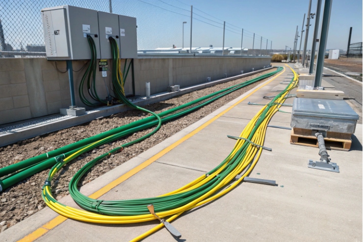
Bonding rules that make SPDs actually work
- Keep SPD connections to PE and bonding bars short and straight.
- Avoid loops. A loop adds inductance, and inductance raises residual voltage.
- Bond all nearby metalwork (cabinet, tray, gland plates) to the same local bonding bar so the surge does not jump across gaps.
Cable shielding and 360° termination
For PoE/Ethernet in noisy plants:
- Use shielded cable when the EMC environment requires it.
- Terminate the shield in a controlled way. A 360° shield bond at a gland plate or shielded connector is stronger than a long drain wire.
- Keep the shield and the SPD earth reference at the same local potential. If not, the shield can carry surge energy into the port.
Surge current will travel through the metal you give it. So the “small hardware” must be corrosion-proof:
- stainless fasteners where exposed to salt
- proper earth tags and bonding straps that are sized and protected
- paint removed only where needed, then protected after assembly
Uptime needs periodic inspection
Offshore and chemical plants change fast. A phone that was bonded correctly at commissioning can lose that bond after years. A simple inspection plan helps:
- visual check for corrosion and loosened lugs
- continuity checks from enclosure lug to bonding bar
- check shield termination points for damage or rework
- confirm no unapproved adaptors were added
| Practice | What it prevents | Why it matters in harsh sites |
|---|---|---|
| Short SPD earth lead | High residual voltage at the load | Protects electronics under surge |
| Single local bonding bar | Potential differences across metalwork | Stops flashover inside cabinets |
| 360° shield termination | Shield acting like an antenna into ports | Stabilizes PoE link and SIP uptime |
| Corrosion-proof joints | Rising resistance over time | Keeps protection stable for years |
| Periodic inspection | Drift from “as-built” condition | Protects warranty and compliance |
A simple client explanation works well here: the SPD is only as good as its connection to earth, and harsh sites attack that connection every day.
Conclusion
Specify surge protection as a layered system: immunity targets for the Ex phone, IEC-rated power and signal SPDs, Ex/IP-safe placement, and low-impedance bonding that stays stable in harsh environments.
Footnotes
-
Defines surge waveforms/test levels to specify device immunity for lightning and switching surges. ↩︎ ↩
-
Power SPD standard for Type selection, tests, and ratings on low-voltage AC systems. ↩︎ ↩
-
Signal-network SPD standard covering telecom/signalling networks, including PoE on the same line. ↩︎ ↩
-
Telecom port resistibility requirements for customer-premises equipment exposed to overvoltages/overcurrents. ↩︎ ↩
-
Resistibility requirements for telecom equipment in access and trunk networks with outside-plant exposure assumptions. ↩︎ ↩
-
Railway EMC emission/immunity expectations for signalling and telecom apparatus in rail environments. ↩︎ ↩
-
Explains lightning electromagnetic impulse protection and LPZ-based surge protection measures inside structures. ↩︎ ↩


