
A phone can pass gas-group and temperature-class checks and still fail in months. Vibration loosens bolts, pulls cables, and opens micro-gaps that turn into downtime.
There is no single “one-size” vibration or seismic standard for explosion-proof telephones. Most projects use IEC 60068 vibration/shock for product durability, and they add seismic standards like IEEE 693 or Telcordia GR-63 only when the site spec demands it.

The standards landscape for vibration and seismic qualification
Explosion-proof is mainly about not becoming an ignition source. That is the core purpose of approvals like ATEX and IECEx 1. Vibration and seismic are different. They are about mechanical survival and stable sealing over time. Plants and EPCs often add these requirements because a phone is only useful when it still works after years of vibration, hose-down, and maintenance.
A practical way to look at it is to separate four layers:
1) Base Ex compliance: the hazardous area protection concept and construction rules (for example, enclosure integrity, fastener control, cable entry control).
2) Environmental durability: vibration, shock, temperature, humidity, corrosion, UV, and ingress.
3) Site-specific hazards: rotating equipment vibration, piping vibration, rail traffic, or offshore motion.
4) Regulated infrastructure needs: substations, telecom rooms, and public safety sites that have formal seismic qualification targets.
In real projects, the common language for testing is IEC 60068 2. MIL-STD-810H is also used, mainly because many owners and integrators understand it and it provides clear profiles. Seismic standards like IEEE 693 and Telcordia GR-63-CORE are typically only required when the phone is part of a substation, control room, or a facility that enforces seismic qualification across installed equipment.
This is the key idea: the standard is only half the answer. The other half is the mounting, the gland choice, and the test fixture. A perfect test report can still hide a weak mounting design. That is why test plans should copy the real mounting method, cable routing, and gland loading as much as possible.
Keep reading if the goal is to write a spec that survives an EPC review and also survives three years in a refinery.
A good spec starts simple. It then adds detail only where failure risk is real.
Which test methods apply—IEC 60068-2-6 vibration, IEC 60068-2-27 shock, and MIL-STD-810H profiles for industrial equipment?
Vibration is not one thing. A phone on a wall near a pump sees different stress than a phone on a skid that travels by truck. If the wrong profile is picked, the test passes but the field fails.
IEC 60068-2-6 (sine vibration) and IEC 60068-2-27 (shock) are common for industrial phones. MIL-STD-810H vibration is useful when a buyer wants defined profiles, random vibration, and clear tailoring rules.

Use IEC 60068 when the goal is product durability
IEC 60068-2-6 is a sinusoidal vibration method. It is often used for resonance search and for sweep tests across a frequency band. It is a good match for rotating machinery vibration and structural resonances. IEC 60068-2-27 is a controlled shock method. It covers pulse shapes and shock severity choices. It is a good match for handling shocks, maintenance knocks, and transport events.
For explosion-proof telephones, these tests should be tied to failure modes:
- Fasteners backing out
- PCB cracks and connector fretting
- Handset hook switch bounce
- Micro-leaks at the door gasket line
- Cable gland loosening and conductor pull-out
A common mistake is to say “test per IEC 60068” and stop there. The test plan still needs the actual severity. Without numbers, two labs can run very different tests and both claim compliance.
Use MIL-STD-810H when the buyer expects random vibration and life-cycle thinking
Guidelines like MIL-STD-810H 3 vibration have strong guidance on tailoring. It is often used to simulate transport, vehicle vibration, and operational vibration with random profiles. Even when the equipment is not military, owners like it because it forces clarity. It also makes people state what the life-cycle is. Is the phone shipped in a crate? Is it mounted near a compressor? Is it on an offshore platform?
MIL-STD-810H is not “harder by default.” It is only harder if the profile is chosen to be harder. So the spec should state the procedure, the profile, the axis method, and the duration.
What to put in the purchase spec
A clean way is to list the method and then list the severity variables that the lab must report.
| Topic | IEC 60068-2-6 (vibration) | IEC 60068-2-27 (shock) | MIL-STD-810H (vibration) |
|---|---|---|---|
| Typical use | Resonance + sine sweep | Handling/transport shock | Random vibration profiles |
| Key variables to state | Frequency range, amplitude or acceleration, sweep rate, time per axis | Pulse shape, g level, duration, shocks per axis | Profile type, PSD levels, duration, axes, mounting |
| Pass criteria | No damage, no loosening, no loss of function | No damage, no loss of sealing, no intermittent faults | Same, plus functional checks during and after |
A short personal note from factory life: one “pass” report once hid a weak hook switch. The fixture clamped the handset cable and removed the real load. The field had cable swing, and the switch failed early. The fix was not a new PCB. The fix was a better strain relief spec and a better fixture rule.
Are seismic qualifications required—IEEE 693 high performance or Telcordia GR-63-CORE Zone 4 for plants and substations?
Seismic can sound optional until a project reviewer asks for it. Then it becomes a gate. Many teams waste time because they do not know when seismic is truly required.
Seismic qualification is usually not a universal requirement for explosion-proof telephones. It becomes required when the site is a substation, a telecom/NEBS environment, or a regulated facility that mandates seismic qualification for installed equipment.
When IEEE 693 makes sense
Standards such as IEEE 693 4 are common in electrical substations. It focuses on seismic qualification of substation equipment and anchorage. If a phone is installed inside a substation control house or yard equipment enclosure system, the owner may ask that the phone and its mounting meet the same seismic performance level as other devices.
The important part is not the standard name. The important part is the required response spectrum level and the mounting method. A phone is light compared to switchgear, but it still fails if the mount and cable entries are weak.
When Telcordia GR-63-CORE Zone 4 makes sense
Qualification under Telcordia GR-63-CORE 5 is tied to NEBS style telecom equipment environments. Zone 4 is often used when owners want a strong “universal” target. This can appear in plant control rooms that adopt telecom-grade racks, network rooms, or when the phone system is part of a broader telecom compliance approach.
If the phone is wall-mounted, a GR-63 style request often translates into “prove the wall mount and cable retention survive a strong shake table test.” It is not only about the electronics.
When seismic is not required, but still smart
Many refineries do not write “IEEE 693” in the phone spec. But they still benefit from:
- Strong mounting hardware rules
- Cable gland locking rules
- Resonance checks on the assembled unit
- Post-vibration ingress checks (especially for outdoor phones)
This is the “middle path.” It costs less than full shake-table qualification but it prevents most vibration-driven failures.
| Site type | Seismic standard most likely to appear | Why it appears | What to do in the phone spec |
|---|---|---|---|
| Substation / utility yard | IEEE 693 | Utility standardization | Define anchorage, bracket strength, and test evidence |
| Telecom/NEBS rooms | Telcordia GR-63-CORE | NEBS physical protection approach | Define rack/wall mounting and cable retention evidence |
| Typical refinery process area | Often none, or project-specific | Focus is uptime, not formal seismic | Use IEC/MIL vibration + mounting rules + inspections |
| Coastal / offshore | Often project-specific | Motion + corrosion | Add corrosion + vibration + ingress retest |
A clean rule works: if the owner says “Zone 4” or “High Performance,” treat it as a formal seismic project and plan for a shake-table test with real mounting.
How should mounting and cable glands be specified to handle continuous vibration—bolt grade, torque, anti-loosening, and strain relief?
A phone can survive any vibration profile on paper. It still fails if the bracket resonates, or if cable weight pulls on the gland, or if bolts slowly walk out.
Continuous vibration success comes from the mechanical stack: bracket stiffness, correct fasteners and torque, proven anti-loosening, and proper strain relief at the gland and inside the enclosure. The phone design and the mount spec must match.
Mounting: treat the bracket as part of the product
For industrial phones, the bracket is not “installation accessory.” It is part of the system. The spec should define:
- Wall thickness or backplate requirement
- Bracket material and corrosion class
- Bolt size and grade, plus washer stack
- Torque method and torque witness marks
- Minimum thread engagement
- Anti-rotation features for the bracket
Bolt grade depends on corrosion and strength needs. Stainless can resist corrosion but can gall. Carbon steel has higher strength but needs coating. The best spec does not force one bolt type for all sites. It defines acceptable options and demands proof of torque retention.
Anti-loosening is not one part. It is a method. Options include prevailing-torque nuts, thread-locking compounds, wedge-lock washers, and safety wire on special builds. The best approach depends on maintenance practice. Some plants hate chemical threadlocker. Some love it. So the spec should state what is allowed.
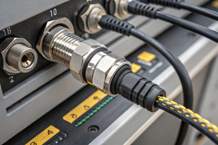
Cable glands: control both sealing and cable load
In hazardous areas, glands must match the Ex concept and the cable type. For vibration, the gland must also control mechanical load. A good gland spec includes:
- Certified gland type for the hazardous area concept
- Cable diameter range and seal type
- Locknut and washer stack, and required tightening method
- A defined external cable clamp distance from the gland
- Internal tie-down points so terminals do not carry cable weight
Strain relief should be described as a measurable requirement, not as a suggestion. For example, the spec can require that external cable be clamped within a given distance from the gland, and that internal conductors have a service loop and a tie-down.
Turn “good practice” into clear acceptance rules
A vibration-ready installation spec can include a checklist that the commissioning team can verify.
| Item | What to specify | What to inspect on site |
|---|---|---|
| Fasteners | Size, grade options, corrosion finish | Correct bolt markings, no mixed hardware |
| Torque | Torque value per fastener set, tool type | Torque mark paint, torque record |
| Anti-loosening | Approved method (washer, nut, compound) | Correct washer stack, correct nut type |
| Bracket stiffness | Min thickness or rib design | No flex by hand, no rattling |
| Cable gland | Certified type, locknut, sealing method | Proper tightening, no gland rotation |
| Strain relief | External clamp + internal tie-down | No cable load on terminals, no sharp bends |
A phone that is “solid” on the bracket usually passes vibration life in the field. A phone that can be wiggled by hand is already sending a warning.
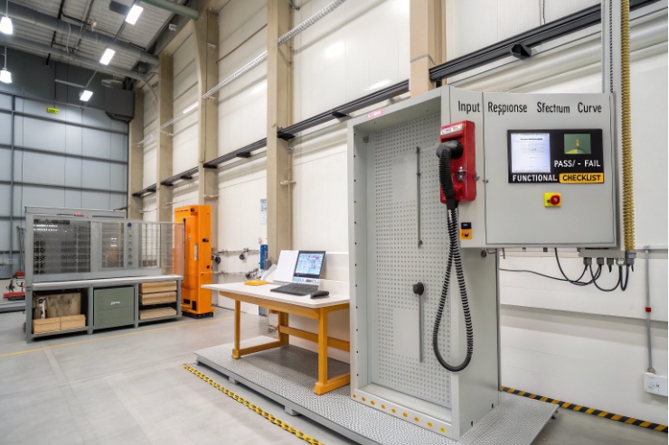
What documentation proves compliance—test reports with spectra, g levels, sweep rates, axes, and resonance checks across temperature extremes?
Buyers do not only want a certificate. They want proof that the test matches the real risk. Auditors also want details. A one-page “PASS” is not enough.
Strong compliance evidence includes a full test report with method references, exact severities, mounting details, axis coverage, resonance findings, and pre/post functional and sealing checks. For harsh sites, add hot and cold conditioning and show results at temperature.
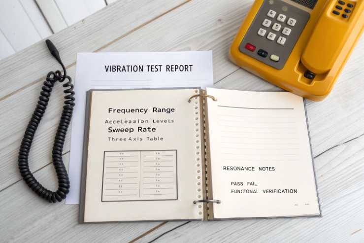
What a good vibration and shock report must include
A useful report lets another lab repeat the test. It also lets an EPC compare suppliers fairly. The report should include:
- Standard and edition year used
- Test equipment and calibration status
- Fixture drawings and photos
- Mounting bolt details and torque used
- Axis definition and axis order
- Functional test plan during and after test
- Clear pass/fail criteria tied to product function
For sine vibration, the report should list frequency range, sweep rate, amplitude method, dwell time, and any resonance search steps. For shock, it should list pulse shape, g level, pulse duration, shocks per axis, and both directions.
For random vibration, the report should include Power Spectral Density 6 plots and overall g RMS, plus duration per axis. If the report does not show the profile curve, it is not a real evidence package.
Resonance checks are not optional for wall-mounted phones
Resonance is where small vibration becomes large movement. A good plan includes identifying the results of a Resonance search 7.
- Resonance search sweep at low level
- Identification of critical frequencies
- Dwell at critical points if the project requires it
- Inspection for loosening, cable rub, and latch bounce
If the mounting bracket shifts resonance, the resonance search must be done with the real bracket and bolt torque. A bare-phone test is not enough.
Across temperature extremes: be honest about what matters
Temperature changes gasket stiffness, plastic stiffness, and cable jacket flexibility. In harsh outdoor sites, vibration plus temperature cycling is where failures appear. Many projects choose one of these approaches:
- Condition at cold, then run vibration
- Condition at hot, then run vibration
- Run vibration at ambient, then run thermal cycling, then repeat a shorter vibration check
The best choice depends on cost and risk. But the report should state the conditioning time, soak temperature, and when the vibration started.
| Evidence item | Why it matters | What “good” looks like |
|---|---|---|
| Severity tables | Prevents hidden soft tests | Exact g, Hz, duration, sweep rate, PSD plots |
| Axis coverage | Avoids missing weak direction | X/Y/Z plus both shock directions |
| Fixture and mounting | Mounting changes results | Photos, drawings, torque records |
| Resonance data | Shows real risk points | Resonant frequencies and response levels |
| Functional checks | Prevents “silent” failures | Call tests, audio, hook switch, LEDs, keypad |
| Post-test sealing check | Vibration can open leaks | IP re-check or water spray check and inspection |
| Temperature conditioning | Field has hot/cold | Soak details and results per condition |
A report package like this makes purchasing easier. It also reduces arguments during FAT and SAT because everyone can see the exact test content.
Conclusion
Use IEC 60068 or MIL-STD-810H for durability. Add IEEE 693 or GR-63 only when the site demands it. Then lock mounting, glands, and reporting details.
⸻
Footnotes
-
Global standards for certifying electrical equipment safe for use in explosive hazardous environments. ↩ ↩
-
International testing standards for measuring the durability of products under various environmental stresses. ↩ ↩
-
A military standard that helps tailor environmental designs and testing limits to specific equipment conditions. ↩ ↩
-
Recommended practices for seismic design and qualification of equipment used in electrical substations. ↩ ↩
-
NEBS physical protection guidelines for telecommunications hardware, including seismic and environmental testing criteria. ↩ ↩
-
A mathematical measure describing how the power of a vibration signal is distributed across frequencies. ↩ ↩
-
An analytical testing process used to find the critical frequencies where mechanical structures vibrate excessively. ↩ ↩


