RS-485 failures feel random. One day the bus is stable, the next day devices drop offline, and everyone blames “bad hardware” instead of wiring and noise.
RS-485 is a differential, balanced serial physical layer that sends data as a voltage difference on a twisted pair. It stays reliable over long distances and noisy sites when topology, termination, and biasing are correct.

RS-485 basics that actually matter in the field
RS-485 is a physical layer, not a full protocol
RS-485 (RS-485 standard overview 1) defines electrical signaling, not messages. It explains how bits travel on the wire, but it does not define addressing, retries, or application data. That is why Modbus/RTU serial protocol specification 2, OSDP access-control protocol 3, DMX512, and many vendor protocols can all run on RS-485. When a project fails, the fix is often not “change the protocol.” The fix is to make the physical bus clean and predictable.
Differential signaling: the real reason it survives noise
RS-485 uses two wires that carry opposite polarity signals. The receiver reads the voltage difference between the pair, not the voltage of one wire to ground. This rejects a lot of noise because interference often couples equally into both conductors. That noise becomes “common-mode,” and the receiver ignores most of it.
This also helps when ground potentials shift across buildings or long cable routes. The pair can float within a tolerated common-mode range, as long as the differential signal stays readable. Still, a shared reference and proper shielding practices reduce risk, especially near VFD motors, elevators, and welding equipment.
Bus topology: a line, not a star
RS-485 expects a linear daisy-chain bus topology 4. Long stubs act like little antennas and reflection points. Reflections smear edges, and the receiver starts seeing false transitions. In practice, short drops are fine, but long branches are not. If a site needs star wiring, a hub, repeater, or a different architecture is usually safer than “hoping it works.”
Termination and biasing: why “it works on the bench” fails on site
A long twisted pair has a characteristic impedance, commonly around 120 Ω. If the bus is not terminated at the ends, signal edges reflect. 120 Ω termination at both ends 5 absorbs energy and stops reflections.
Bias (failsafe) resistors set an idle state so the line does not float when nobody is driving. Without bias, the bus can drift into random logic levels and create phantom bytes. Many modern transceivers include failsafe features, but relying on them alone is risky on long, noisy runs. I prefer defined biasing on the bus, with only one bias point to avoid fighting pull-ups. A practical reference for sizing this network is external fail-safe biasing 6.
| RS-485 design item | Best practice | What breaks if ignored |
|---|---|---|
| Cable | 120 Ω twisted pair | Noise pickup and reflections |
| Topology | Linear daisy-chain | Random CRC errors, dropouts |
| Termination | 120 Ω at both ends | Edge ringing, bad framing |
| Biasing | One defined bias point | Phantom data, unstable idle |
| Stubs | Keep drops short | Intermittent errors at speed |
| Node loading | Respect unit-load limits | Weak signal, bus collapse |
RS-485 is simple, but it is strict about physics. Once the bus is built correctly, the protocol on top becomes easier to debug.
The next step is understanding why RS-485 is still a favorite in industrial intercom deployments where noise and distance are normal.
What RS-485 features make it reliable for industrial intercoms?
Industrial sites punish audio and control links. Motors switch, relays arc, and ground shifts appear. A weak interface fails slowly and unpredictably.
RS-485 stays reliable in industrial intercoms because differential signaling rejects noise, multi-drop wiring reduces cable complexity, and common protection options like isolation and surge clamps fit harsh electrical environments.
Noise immunity that fits real factories
Intercom deployments often sit near electrical noise sources: elevator motors, HVAC drives, and paging amplifiers. RS-485 differential signaling helps because induced noise tends to couple into both wires. The receiver looks at the difference and ignores much of that coupled noise. This is why RS-485 often works where single-ended UART over long wire fails.
Common-mode tolerance helps across long routes
Long cable routes create ground potential differences. RS-485 receivers tolerate significant common-mode voltage, which gives breathing room. Still, it is not a license to ignore grounding. A clean reference, shield strategy, and isolation where needed keep things stable.
Multi-drop reduces wiring cost and points of failure
Industrial intercom networks often need many endpoints: call boxes, stations, zone panels, and I/O expanders. RS-485 supports multi-drop, so one bus can serve many nodes. That reduces cable runs and simplifies troubleshooting. It also makes expansions easier, as long as node loading and topology rules are respected.
Isolation and surge protection are easy to add
For industrial intercoms, the best RS-485 ports include:
- Galvanic isolation to break ground loops
- TVS diodes to handle ESD and surges
- Proper transient protection for long outdoor runs
These hardware choices usually matter more than baud rate. A fast bus that resets during transients is worse than a slower bus that stays up all year.
Deterministic behavior with master-slave protocols
Many RS-485 systems use a master poller. The master requests and a slave responds. This avoids collisions and makes traffic predictable. For industrial intercom control signaling, predictability beats peak bandwidth.
| Industrial risk | RS-485 strength | Practical design tip |
|---|---|---|
| EMI from motors | Differential rejection | Use twisted pair, route away from power |
| Ground shifts | Common-mode tolerance | Add isolation on long building links |
| Many endpoints | Multi-drop bus | Keep linear topology, limit stubs |
| ESD/lightning | Protection-friendly | Use TVS + shield + earth strategy |
| Maintenance | Simple physical layer | Label A/B clearly, document term points |
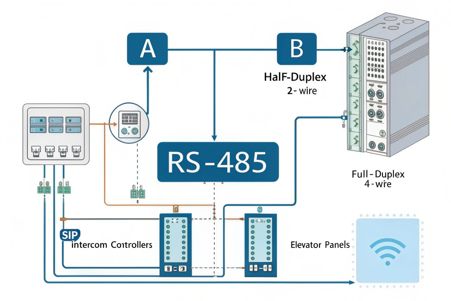
In many deployments, RS-485 becomes the “control backbone” while SIP carries voice and video over IP. That split keeps audio modern and control wiring tough.
Now it helps to get practical about wiring, because 2-wire and 4-wire RS-485 are often confused during installation.
How do 2-wire vs 4-wire RS-485 wiring and termination work?
RS-485 wiring mistakes rarely fail instantly. They create intermittent issues that look like software bugs. The fastest fix is choosing the right wiring mode and terminating correctly.
2-wire RS-485 is half-duplex on one differential pair, with termination at both ends and careful driver turn-around timing. 4-wire RS-485 uses separate TX and RX pairs for full-duplex, with termination on each pair’s ends.
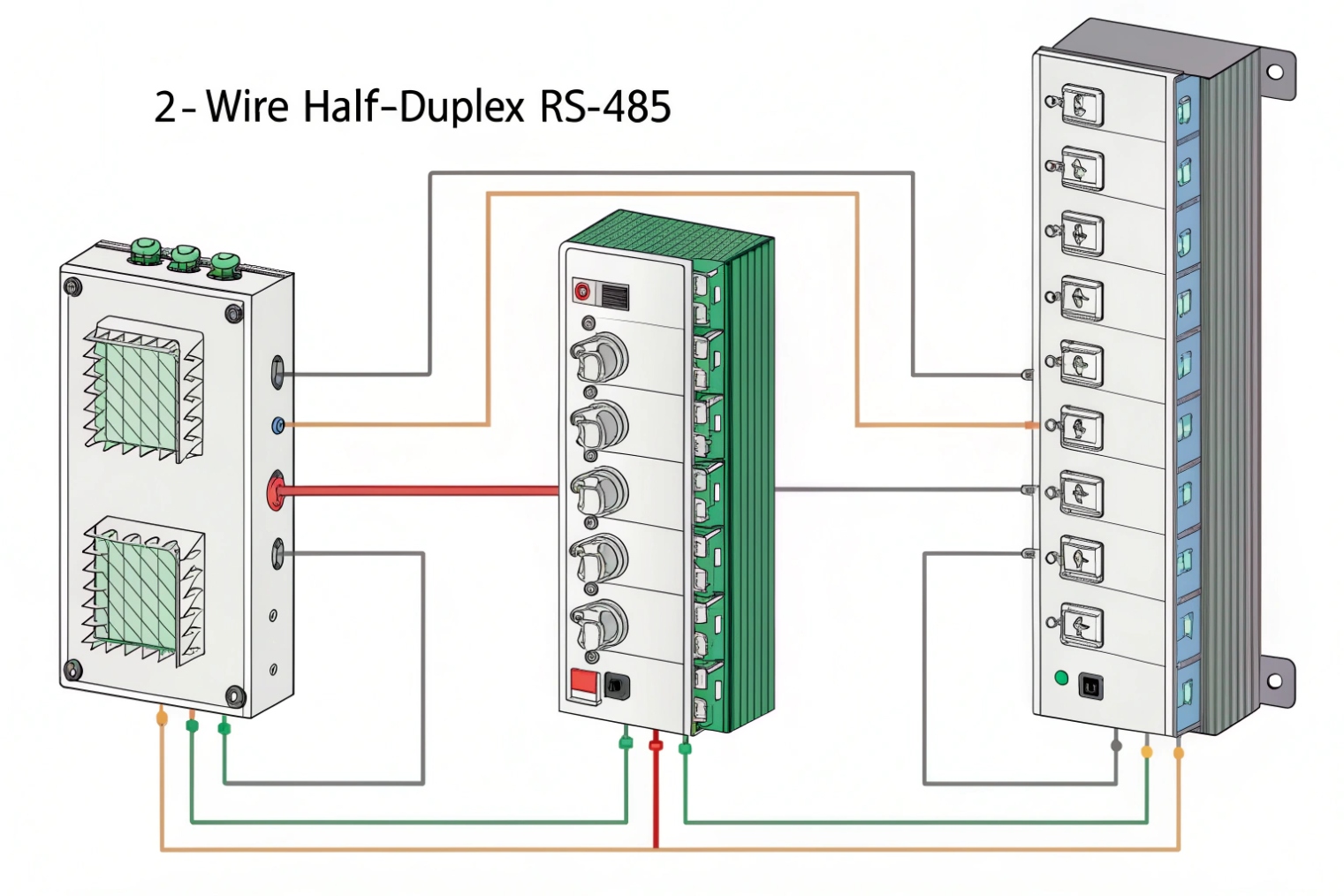
In 2-wire RS-485, every node shares the same A/B pair. Only one device should drive the bus at a time. This requires driver-enable control and correct turn-around timing. Many USB adapters and industrial interfaces provide automatic direction control, which reduces mistakes, but the bus still needs discipline from the protocol.
Termination goes at the two physical ends of the cable run. Biasing should be defined in one place. Stubs should stay short. If there is a star wiring layout, the “ends” become unclear, and termination becomes guesswork. That is when random errors appear.
4-wire (full-duplex): separate transmit and receive pairs
In 4-wire RS-485, the master can transmit on one pair while receiving on the other. Slaves typically transmit back on the master’s receive pair. This can simplify timing, and it can reduce collision risk, but it adds cable and termination complexity. Each pair needs termination at its ends. In practice, 4-wire makes sense when the system is designed for it end-to-end and when full-duplex behavior is actually used.
Polarity labeling: A/B is not universal
One of the most common field problems is A/B labeling differences. Some vendors label A as negative (D−), some label A as positive. Matching polarity matters more than names. If polarity is reversed, communication may fail or look like garbage bytes. A simple swap test can confirm polarity quickly when documentation is unclear.
Termination and stubs: where most installs go wrong
I keep two simple rules:
- Terminate at the two bus ends only.
- Avoid long stubs. If a drop must exist, keep it short.
A bus with too many terminators loads the line and reduces differential voltage. A bus with no terminators rings. Both problems show up as CRC errors or missing replies.
| Wiring mode | Conductors | Duplex | Termination points | Best use case |
|---|---|---|---|---|
| 2-wire RS-485 | 1 pair + reference | Half-duplex | At the two bus ends | Multi-drop control networks |
| 4-wire RS-485 | 2 pairs + reference | Full-duplex | Each pair at its ends | Designed full-duplex systems |
| Mixed/incorrect | Varies | Unstable | Often wrong | Intermittent faults and retries |
When wiring and termination are correct, troubleshooting shifts from “random failures” to clear, repeatable checks. That is where the right test tools save time.
Which tools test RS-485: multimeter, oscilloscope, protocol analyzers?
RS-485 debugging is easier when checks are layered. I start with power and wiring, then verify signal integrity, then verify protocol frames. Skipping steps wastes time.
Use a multimeter for continuity and bias voltage checks, an oscilloscope for differential waveform and reflections, and a protocol analyzer or USB-RS485 adapter to confirm framing, timing, and addressing.
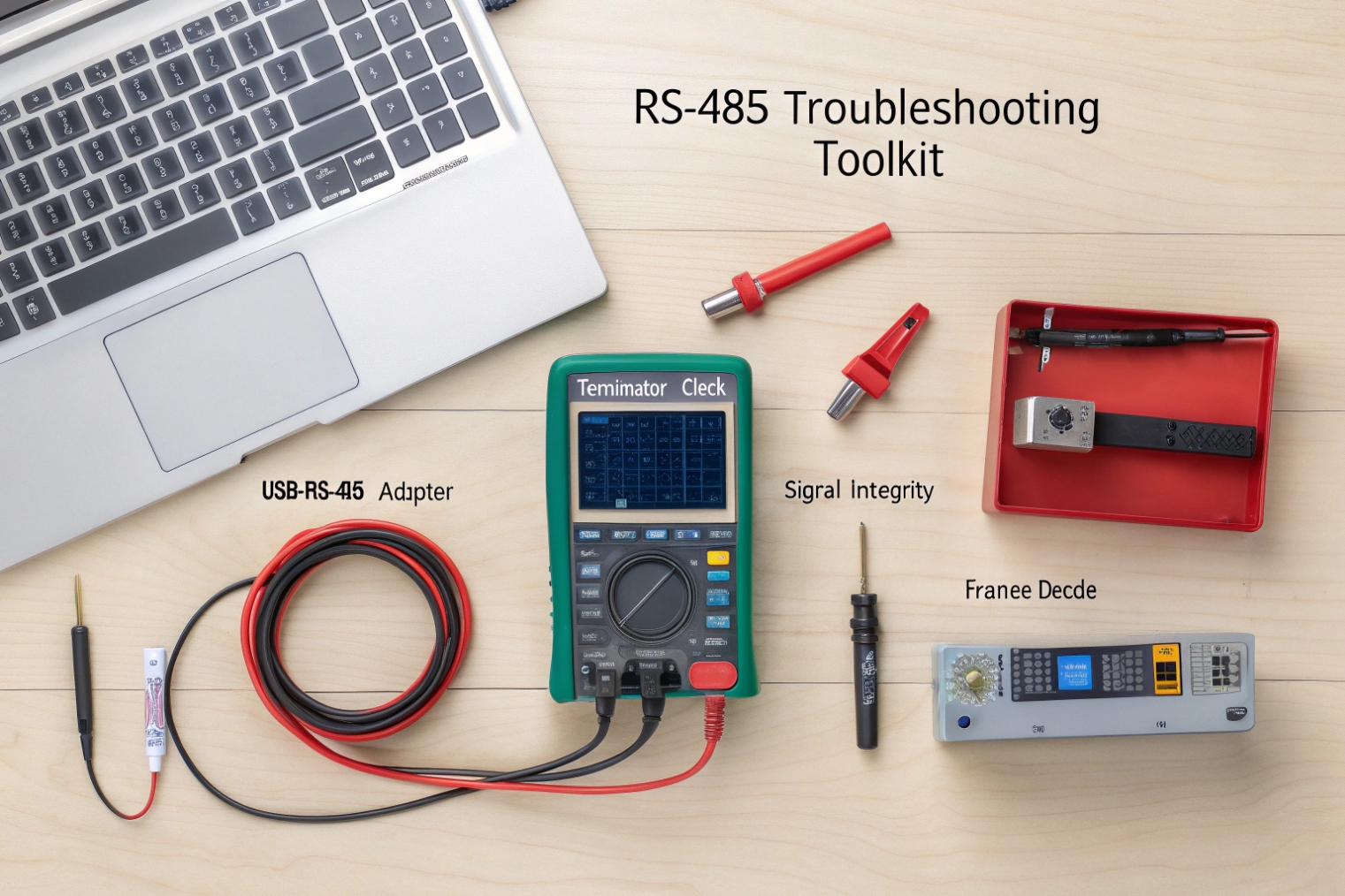
Multimeter: confirm basics before decoding bytes
A multimeter helps with:
- Continuity on A/B and reference
- Shorts between conductors
- Power and ground integrity
- Idle bias voltage presence (rough check)
It will not show reflections or jitter, but it catches the common mistakes: broken wires, swapped conductors, missing reference, and wrong supply.
Oscilloscope: see the physics
A scope is the fastest way to confirm termination problems. With a scope, I look for:
- Differential amplitude that is too small (overloading, too many nodes, too many terminators)
- Ringing and reflections (missing termination, long stubs)
- Noisy common-mode behavior (bad shielding, ground issues)
- Driver contention (two devices driving at once)
A differential probe is ideal. Without it, two channels and a math subtraction can work, but the setup must be careful.
Protocol analyzer: confirm the talk makes sense
Once the electrical layer looks healthy, decoding frames matters. A protocol analyzer or a PC with a USB-RS485 adapter can capture bytes. Then it is possible to confirm:
- Correct baud rate and parity
- Addressing
- Response timing
- CRC errors
- Collisions or repeated retries
For Modbus/RTU and similar systems, CRC error counts often point back to wiring problems. For OSDP, retries and timeouts can point to polarity, termination, or bus loading issues.
| Tool | What it verifies well | What it cannot prove |
|---|---|---|
| Multimeter | Continuity, shorts, power | Reflections, edge ringing |
| Oscilloscope | Signal shape, noise, termination | High-level protocol logic |
| USB-RS485 + software | Baud/parity, frame decode | True signal integrity if decoding “barely works” |
| Dedicated analyzer | Timing, collisions, statistics | Cable routing and grounding quality |
A disciplined test method makes RS-485 support scalable. It also helps separate “bus issues” from “application issues,” which matters in access control and elevator integrations.
Now the last piece is context: where RS-485 actually shows up in modern security, elevators, and paging projects.
Where is RS-485 used in access control, elevators, and paging?
Many systems feel “IP-first,” but RS-485 still sits inside the building as a tough control spine. It is used where wiring needs to be simple, long, and noise-resistant.
RS-485 is common in access control reader links and I/O expanders, elevator control interfaces, and paging zone controllers. It often bridges to IP through gateways or controllers, while the RS-485 segment stays local and robust.
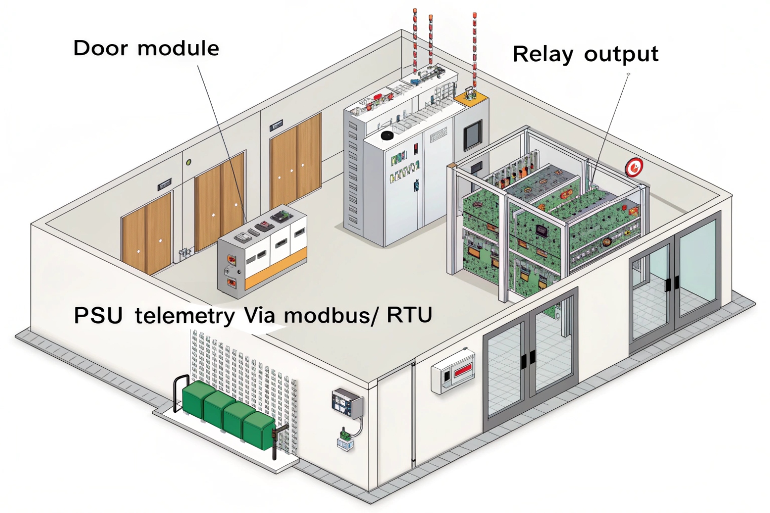
Access control: readers, modules, and secure upgrades
Access control systems often use RS-485 for field modules and reader communications. OSDP is a major example because it brings secure, bidirectional communication over RS-485. Even when the main controller is IP, RS-485 often connects:
- Reader interfaces
- Door I/O boards
- Expansion modules
- Keypads and peripherals
This keeps door wiring stable even when network switches change.
Elevators: car stations, controllers, and emergency integration
Elevator environments are electrically noisy and mechanically harsh. RS-485 is used in many elevator subsystems because it survives long cable runs and EMI. Typical use cases include:
- Car operating panels and service interfaces
- Status and control points for building systems
- Emergency phone and alarm integration paths (often through vendor gateways)
Paging and PAGA: zones and remote controllers
Paging systems often use RS-485 for zone control, amplifier supervision, and remote panels. A central paging controller may speak to multiple remote units over RS-485, especially in plants, stations, tunnels, and campuses. The audio might travel on a different medium (analog line, IP audio, or dedicated audio cabling), while RS-485 carries control and status.
SIP intercom projects: a practical bridge pattern
In SIP intercom deployments, it is common to keep voice and video on IP while using RS-485 for local control or integration:
- A SIP intercom connects to an access control controller over IP.
- The access controller talks to door modules or readers over RS-485.
- A gateway can bridge IP commands to RS-485 devices for legacy zones.
This approach keeps the building edge stable and reduces the amount of IP hardware in harsh locations. In many deployments, that design lowers failure rates and simplifies maintenance.
| Vertical | Typical RS-485 devices | Common upper protocol | Integration note |
|---|---|---|---|
| Access control | Door modules, readers, expanders | OSDP, vendor protocols | IP controllers often bridge to RS-485 |
| Elevators | Panels, status interfaces, gateways | Vendor serial protocols | Careful grounding and isolation help |
| Paging/PAGA | Zone controllers, remote panels | Vendor protocols, Modbus-like | Keep topology linear, protect against surges |
| Industrial intercom | I/O modules, call box control | Vendor protocols | RS-485 control + SIP media is a stable split |
RS-485 keeps showing up because it solves a specific field problem: long, noisy, multi-node control wiring that must be cheap and predictable. When installed with correct topology, termination, and protection, it becomes very boring. That “boring” is exactly what industrial systems need.
Conclusion
RS-485 is a differential serial physical layer that stays stable over distance and noise. Correct topology, termination, biasing, and testing tools turn it into a reliable backbone for intercom, access, elevator, and paging control.
Footnotes
-
RS-485 overview: electrical characteristics, node limits, and signaling basics for long, noisy serial buses. ↩ ↩
-
Official Modbus serial-line guide for framing, timing, and CRC—useful when troubleshooting noisy RS-485 links. ↩ ↩
-
SIA’s OSDP resources explain secure channel, wiring guidance, and troubleshooting for readers on RS-485. ↩ ↩
-
Installation-focused guidance on daisy-chain topology, stub limits, and where termination belongs on real RS-485 buses. ↩ ↩
-
Shows when and how to terminate RS-485 lines to prevent reflections and framing errors on long cable runs. ↩ ↩
-
Shows how to size bias networks so idle lines don’t float and receivers avoid false bits on multi-drop buses. ↩ ↩


